Coarse and Fine volume circuit

Thread Starter

drjackool

Joined May 23, 2021
62
Hi
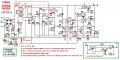
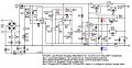
I build this power supply circuit and works fine, but I want insread one POT for adjusting voltage (P1 is 10K), using two POT for coarse and fine. I just simply connected two pot in series one 1K and another 10K but problem is the out is not linear! What is correct circuit for it?
1000009884.png
My current coarse fine:
1000010191.png
Thanks
 
Last edited:

crutschow

Joined Mar 14, 2008
38,316
You could use the connection below, but they both should be 10kΩ pots for your circuit.
R4 gives essentially the same fine-adjustment range of about 10% of full-scale for any setting of R1.
You can alter the fine-adjustment range by changing the value of R3. For example 200kΩ would give about 5% of full-scale adjustment.

Otherwise you could use a 10-turn pot for better resolution.

1743008487748.png
 
Last edited:

MisterBill2

Joined Jan 23, 2018
27,164
It is entirely possible that the variable resistor you added is not a linear taper device, but rather an "audio taper" potentiometer. In addition, why does the adjustment of a variable power supply need to be linear?? Usually I adjust a voltage by measuring the voltage delivered, NOT by looking at a knob position.
 

MisterBill2

Joined Jan 23, 2018
27,164
Of course, IF the control pot IS an actual volume control variable, it certainly will not be linear, unless it is in dBs!!! "Volume controls are "log-taper" devices, certainly non-linear.
In addition!! there is no promise that any output voltage adjustment resistor in a regulator circuit will provide a uniform change in output voltage for a give increment of rotation. AND, for most of us that does not matter at all.
 

crutschow

Joined Mar 14, 2008
38,316
Of course, IF the control pot IS an actual volume control variable, it certainly will not be linear, unless it is in dBs!!! "Volume controls are "log-taper" devices, certainly non-linear.
In addition!! there is no promise that any output voltage adjustment resistor in a regulator circuit will provide a uniform change in output voltage for a give increment of rotation. AND, for most of us that does not matter at all.
Did you not understand my post #4?
It's not the linearity of adjustment with pot rotation that's the problem.
 

MisterBill2

Joined Jan 23, 2018
27,164
Did you not understand my post #4?
It's not the linearity of adjustment with pot rotation that's the problem.
OK, NOW I see the complaint: The TS wants the fin control to change the output by a constant number of volts instead of changing the output a constant percentage of that output. Certainly that is a very different function.
I suggest inserting the fins adjustment variable resistor between the ten K pot terminal "10" and the circuit it is tied to. THAT will increment the setpoint up and down. by a constant amount.instead of by a variable amount.
 

crutschow

Joined Mar 14, 2008
38,316
I suggest inserting the fins adjustment variable resistor between the ten K pot terminal "10" and the circuit it is tied to. THAT will increment the setpoint up and down. by a constant amount.instead of by a variable amount.
The circuit I posted does that.

Don't see how yours can(?),
Can you post exactly how it's connected?
 

MisterBill2

Joined Jan 23, 2018
27,164
LOOK AT THE CIRCUIT SHOWN IN POST #1 !! Then look at the voltage adjust resistor with three terminals, 5, 12, and 10!!
Now visualize a variable fine adjustment resistor between that terminal #10 and the horizontal line just below it, instead of the short line there now.
AND, LOOK AT THE SMALL DETAIL JUST BELOW THAT, but visualize the fine adjust 1K resistor R1,located beneath R2 instead of above!!!

That WILL make a difference!! Unfortunately any current flowing out thru terminal 12 will tend to have some effect. The reason it will be different is because the change in the voltage at terminal 12 will be shifted by the same amount,
 

crutschow

Joined Mar 14, 2008
38,316
visualize the fine adjust 1K resistor R1,located beneath R2 instead of above!!!
And visualizing further, you can see that gives zero fine adjustment range at the maximum voltage setting and 10% adjustment range at the zero volt setting!!!
 
Last edited:

MisterBill2

Joined Jan 23, 2018
27,164
Indeed, I forgot to mention that it also needs a separate series resistor above the voltage adjust pot. I was thinking about that voltage adjust pot being current driven. You caught my error. It was a bit late at the time.
The fine adjustment control should be in series with R8.
 

schmitt trigger

Joined Jul 12, 2010
2,027
I believe that the confusion started by using the word “volume” which is mostly associated with audio terminology, which requires a log taper pot.
That word should have been “voltage adjustment”..
 

MisterBill2

Joined Jan 23, 2018
27,164
I believe that the confusion started by using the word “volume” which is mostly associated with audio terminology, which requires a log taper pot.
That word should have been “voltage adjustment”..
I understood and commented on that much earlier in the thread. Certainly you are correct, "audio taper" is, I think, close to linear IN DECIBELS.
But I still wonder about what sort of application or use would demand that sort of performance. OR MAYBE it is a top-secret application. We do see a few of those, where only a small bit of a system is revealed,
 

Craps1956

Joined Aug 21, 2015
38
Not commenting about the 'course/fine adjustment' but just some information on this circuit. Hope it is helpful or of some interest. This circuit has been discussed many times over the last 10 years or so in other threads. There have been many improvements mainly contributed by Audio Guru and other members. I have successfully assembled it with the attached modifications (Rev7) and it works very well.
 

Attachments

MrAl

Joined Jun 17, 2014
13,667
Hello to all,

I am not sure I am seeing the problem with the solution in post #1, although I like the one posted by Crutschow too although I did not analyze that one in detail yet.

Let's first think about this a little. What is a percentage.
A percentage here is the percent of output relative to the setting of the course adjustment by the 10k pot. This means that if the top end range setting of the 1k pot is 1v then the bottom end should be 0.9v, and if the top end is 0.1v, then the bottom end should be 0.09 volts because 0.01 is 10 percent of 0.1 volts.
That's the way it looks like it works using the solution in the first post.
Is this the desirable action or not?
This also goes with the assumption that this voltage reflects the true output changes so that when we vary this voltage by 10 percent the output also changes by 10 percent.


The formula (with no static load and that seems to agree with the given schematic) is:
Vout=Vin*R2b/(R1+R2)
where in that first post:
R2=10k,
R2b is the bottom section of R2 (goes from 0 to 10k while the top section goes from 10k to 0), and
R1 is the 1k pot in series with R2 and acts as a rheostat.

Since R2=10k fixed (total resistance of the 10k pot) we can set R2=10 and work R2b in units of kOhms also.

Using a 1v input as reference...
With R2b set to 1, with R1=0 we get 0.1 and with R1=1 we get 0.091 which is very close to a 10 percent decrease.
With R2b set to 10, with R1=0 we get 1.00 and with R1=1 we get 0.91 which is close to a 10 percent decrease.
With R2b set to 5, with R1=0 we get 0.500 and with R1=1 we get 0.454 which is close to a 10 percent decrease.
With R2b set to 7.5, with R1=0 we get 0.75 and with R1=1 we get 0.682 which is close to a 10 percent decrease.
With R2b set to 2.5, with R1=0 we get 0.25 and with R1=1 we get 0.023 which is close to a 10 percent decrrease.
There should be no anomalies between any of these test points as the generated 3d surface looks flat.

As it turns out, the decrease is not exactly 10 percent it is 9.1 percent, but that should be OK I would think.

Feel free to correct this I could have easily made a mistake in the early morning :)
It's also possible that I have the wrong circuit idealities in mind.

As a final note, this is the way one fairly expensive power supply does it. It has a switcher front end (adjusts automatically) and a linear back end which is adjusted as per post #1.
I mentioned that it was expensive, about $250.00 USD, but I don't think we should really let that be a consideration as to the quality of the output voltage adjustment technique ... let the math (or any corrected math) speak for itself instead.
 
Last edited:

MisterBill2

Joined Jan 23, 2018
27,164
It still seems unusual to demand a constant voltage change per unit of rotation of the fine adjustment control. What sort of application would demand that??? The need for exact setting is why many power supplies have output voltage meters.
 

crutschow

Joined Mar 14, 2008
38,316
It still seems unusual to demand a constant voltage change per unit of rotation of the fine adjustment control. What sort of application would demand that???
Don't think it's a "demand" so much as a preference for the one using the power supply.
The need for exact setting is why many power supplies have output voltage meters.
Achieving that exact setting may be difficult for the resolution of a standard pot, thus the desire for a fine tuning pot.
 
Top