Finding right relay (or proper wiring)

Thread Starter

Gewoon.Jorik

Joined May 10, 2025
7
Hello everybody,

So I can't seem to figure this one out.
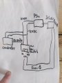
I have a card reader (Nayax Onyx) with a constant 9v on pulse cable.

I have a 12v relay switch.
https://www.otronic.nl/nl/relais-module-12v-2-kanaals.html

Connected 9v pulse cable to IN, 12vdc and -12vdc to power the relay coil.
Jumper set to low/ground.
When card reader detects card the pulse line grounds.
I don't think the next matters, two 5v wires on the switch side of the relay, normally open.

So I had the relay detect the pulse to ground once or twice and then stopped working.

My main question is does the IN of 9v need to be 12v (and if so how could I implement that?) because if pulse is grounded the relay will detect 9v still as low and keep coil active?
I am unfamiliar with Amperages so could this have fried the relay?
 

Tonyr1084

Joined Sep 24, 2015
9,744
Welcome to AAC.

Not enough info for ME to follow. But that's me.

If it worked once or twice then quit - I'd suspect you've blown something out. A schematic diagram of how you're connecting things together along with information on what components or devices you're using would be helpful. At least to me it would.
 

Tonyr1084

Joined Sep 24, 2015
9,744
Since I don't read German (or if I'm wrong abut the language) the data sheet, if they give you one, should show what the minimum "IN" voltages are. Since there are two relays and two "IN"s, have you tried the second relay and IN(put)? It COULD just be a cheaply made module.

I don't know that 9V pulsed would be an issue for a 12V module but my guess is that it shouldn't. But again, I need more information.
 

sghioto

Joined Dec 31, 2017
8,633
Check the voltage at the input terminal from the card reader when on and off.
Does the other relay work?
Is the negative side of the card reader connected to -12V?
 
Last edited:

sghioto

Joined Dec 31, 2017
8,633
Wiring looks correct.
Have you measured the voltage on the input terminal of the relay module when the card reader is activated?
 
Last edited:

Thread Starter

Gewoon.Jorik

Joined May 10, 2025
7
I'll have to do it again later since I haven't tried it since it stopped working (forgot MM)
Last time it did read 9vdc and dropped to 0 for the duration of the pulse (25ms)
 

MisterBill2

Joined Jan 23, 2018
27,164
Wiring looks correct.
Have you measured the voltage on the input terminal of the relay module when the card reader is activated?
That circuit did not look correct to me, based on my understanding of the description. AND it also did not look like a circuit diagram, but rather more like a block diagram. A circuit diagram shows details.
 

Tonyr1084

Joined Sep 24, 2015
9,744
Does this help?
Screenshot 2025-05-11 at 8.04.51 AM.png
Downward pointing arrows represent the negative side of the power supply. Interconnecting all the negative lines serves to muddle up the schematic. Assume the positive connection from the power supply to be going to the positive connections of the driver, controller and relay module. The 5VDC is connected to the relay contacts Common and Normally Open so that when there's a 9V pulse the relay should momentarily close; according to the TS comments.

And to all - Happy Mom's Day.
 
Last edited:

MisterBill2

Joined Jan 23, 2018
27,164
Does this help?
View attachment 348954
Downward pointing arrows represent the negative side of the power supply. Interconnecting all the negative lines serves to muddle up the schematic. Assume the positive connection from the power supply to be going to the positive connections of the driver, controller and relay module. The 5VDC is connected to the relay contacts Common and Normally Open so that when there's a 9V pulse the relay should momentarily close; according to the TS comments.
Does that neat block diagram tell everybody just where to make the connections?? I don't think so! It does not even describe which way the signals go. Some of us can figure it out, but only with additional knowledge.
 

Tonyr1084

Joined Sep 24, 2015
9,744
Drawing (post #16) is what I make of the TS drawing. According to the TS statements the controller delivers a 9V pulse to the relay module. The driver functionality is as yet unknown. Does it open a lock? Or something else? Whatever is coming from the Driver it is activated by the closure of what is identified as a 5VDC line connected to the relay contacts.

FWIW, it looks like it should do whatever it is supposed to be doing. The 9V closes the relay. The relay tells the driver there's a closure. The driver does whatever it does. That's as far as I can get.
 

sghioto

Joined Dec 31, 2017
8,633
Maybe this will help:
Don't know what that Driver Board is but apparently it's activated when the relay contacts close.
The TS said it worked a couple of times then stopped working but if the signal input (IN) on the relay module is connected to -DC the relay activates as it should.
That tells me there is a problem with the Card Reader.
1746974381498.png
 
Last edited:

sagor

Joined Mar 10, 2019
1,046
Those relays, when set to a "L" trigger, provide the DC+ via a 2.2k resistor (approx) and optoisolator to the "IN" pin. That is, it supplies the voltage at the "IN" pin for grounding to trigger the relay.
So the question is, can the card reader handle the approx. 9V (12V less opto LED voltage drop) at 4 to 5mA? If the card reader expected a 5V TTL level signal, then the TS may have blown the interface of the card reader. One would think the card reader interface would have a buffer device like a transistor or MOSFET to drive that line low for 25ms. In that case, that would be the device that has failed.
Since it worked twice, then failed, I agree with sghioto, the card reader interface may be at fault.
 
Last edited:
Top