Finding intermittent faults in PIC PCB Peripherals OSHONSOFT

Thread Starter

camerart

Joined Feb 25, 2013
3,724
Hi J and J2,
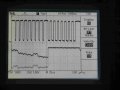
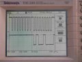
I just disconnected the wire from the MISO on the COMP.
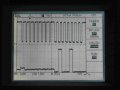
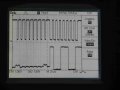
The MOSI shows 2.64V
The MISO shows 0V.
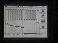
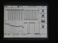
There is a shadow at the disconnected PIC MOSI end, so I will re-wire the COMP again, and re-check.

When I originally connected the COMP VID to VDD, I must have read the D/S carefully, and seen what you both say that the MISO should be at 2.54V. {I also had advice from another person on this forum, that I don't remember the name, sorry)
Thanks.
C
 

Thread Starter

camerart

Joined Feb 25, 2013
3,724
PIC 18F4620 has a minimum supply voltage 4.2 V !
Hi J,
Doh!!!
It looks like my best option is to change to 18LF4620. (a bit pricey though) :(
I spent ages, changing and selecting PICs for this project, and I do recall, the LF type, but I must have slid out of the thought as I bought the last lot. I've got a pile of unused PICs now:(
Thanks.
C
 

bertus

Joined Apr 5, 2008
22,270
Hello,

Could it be that a low voltage detection is playing you parts.
The device seems to be designed for 5 Volts, but may react erratic at 3.3 Volts.

Bertus
 

Thread Starter

camerart

Joined Feb 25, 2013
3,724
Hello,

Could it be that a low voltage detection is playing you parts.
The device seems to be designed for 5 Volts, but may react erratic at 3.3 Volts.

Bertus
Hi J and B,
Ok, as the 18F4620 18F4520 pics have reliably run, I'll persevere, at least while I'm testing. (Remind me if a problem later could be related, please)

I was checking the wiring, and Oscilloscope signals, but as usual got mixed up with SDI one end with SDI the other, so I'm going to only use MOSI and MISO from now on, then if I'm testing halfway along the wire, it will correspond. I'll rewrite all labels, and hope this error is my misreading. (To all of our frustrations)
C.
 

Thread Starter

camerart

Joined Feb 25, 2013
3,724
Hi,
The wiring on the main PCB, is correct.
I tried the other working PCB. With the MISO disconnected at the COMP end. At the COMP end: Here is the MOSI and MISO READings.

Even though it's working, the MISO is raggy, but the MOSI is clear, which points to the COMP not outputting a good signal.

I'll recheck the COMP setting etc.
EDIT: Here's the Microchip specifications again, which are misleading:
C
 

Attachments

Last edited:

Thread Starter

camerart

Joined Feb 25, 2013
3,724
If the MISO is disconnected from the compass, how can you see anything at the PIC.
Capacitive coupling?
Hi J,
I was testing the COMP output without any chance of shorting or other problems, as suggested earlier.
C
 

Thread Starter

camerart

Joined Feb 25, 2013
3,724
You said in #107:
"With the MISO disconnected at the COMP end. At the COMP end: Here is the MOSI and MISO READings."
Hi J,
True, the MOSI from the PIC is connected to the COMP, therefore, the COMP is seeing the DATA from the PIC.
The MISO is disconnected from the COMP, but the MISO at the COMP is connected to the Oscilloscope, showing the COMP output.
(I am open to correction, if I'm mixed up)
C
 

jjw

Joined Dec 24, 2013
823
The MISO was better earlier.
Your scope settings look not ok?
The signal is set to video and trigger at line sync.
Is the coupling DC?
Add the SPI clock to the same picture with the MISO.
 
Last edited:

Thread Starter

camerart

Joined Feb 25, 2013
3,724
The MISO was better earlier.
Your scope settings look not ok?
The signal is set to video and trigger at line sync.
Is the coupling DC?
Add the SPI clock to the same picture with the MISO.
Hi J,
The Osc was showing trigger, now Channels.

Here's the 1st READ 0x80 and give 0x48 COMP I.D.

As #107 this is the test PCB. It looks different today? There is no READ input to the PIC. (as error)
C
 

Attachments

Thread Starter

camerart

Joined Feb 25, 2013
3,724
Has the ID been always correct?
Try to read only the six values of X.lb, X.hb, Y.lb ...
Hi J,
See #80, I think it's always READ 48.

READing all 6x Registers is asking for mixups :) but I think these maybe correct.

They don't look good, though.
C.
 

Attachments

jjw

Joined Dec 24, 2013
823
There are some ghost pulses in MOSI.
Can you make the trigger from the first falling edge clock pulse and single sweep.
 

Thread Starter

camerart

Joined Feb 25, 2013
3,724
There are some ghost pulses in MOSI.
Can you make the trigger from the first falling edge clock pulse and single sweep.
Hi J,
We may change the trigger to the 1st falling edge, which is contrary to the AK8963C D/S and it may work, and be a 'red herring', and also confusing for me. I would prefer to keep it correctly triggered on rising edges. What do you think?

Bear in mind there are >1 PCBs and COMPS, so I'll OSC test different combinations first, as they're all not working properly.

EDIT: 1st image TEST PCB (as#115) (Note short program, only 1/peripheral 'COMP') in between 2 of the BYTES, showing odd MOSI GHOST.

4x images from either COMP1 or COMP3 module, and either connected or disconnected from MISO at COMP end, all on PCB1 (MAIN). See title

If we leave the TEST PCB for now, as there may be something else wrong.

As when the MISO is connected, the voltage goes down, and remembering that the PIC is on the edge of the voltage allowed, I again think it could need a voltage leveler, up to 3.3V which I'll order.

NOTE: The IDLE level of the DATA is HIGH on one PIC and LOW on the other, same PCB, same program??

C.
 

Attachments

Last edited:

jjw

Joined Dec 24, 2013
823
The oscilloscope can be triggered at both edges.
When triggered at falling edge, you can see when clock goes low for the first time. It has nothing to do with the edge which is correct for AK8963 to read or write data.
Remember that compass high level output should be 2.64V minimum.
Has the scope zero level been the same in all pictures?
I am quite certain that something loads the MISO so that levels shift and/or are two low.
Are the other devices deselected when reading?
 

Thread Starter

camerart

Joined Feb 25, 2013
3,724
The oscilloscope can be triggered at both edges.
When triggered at falling edge, you can see when clock goes low for the first time. It has nothing to do with the edge which is correct for AK8963 to read or write data.
Remember that compass high level output should be 2.64V minimum.
Has the scope zero level been the same in all pictures?
I am quite certain that something loads the MISO so that levels shift and/or are two low.
Are the other devices deselected when reading?
Hi J,
I've changed the SCOPE to Falling edge, with the trigger 1/2 way up the CLK. I'm not sure if it has been there all the time.
I'm not too sure about previous READings, but with the MISO disconnected the Voltage goes up to 3.3V and the MISO Slope disappears. With it disconnected, the MISO slope appears, and the voltage goes down to app 1.65V

The disconnected MISO (Only connected at the PIC end) resistance to any PIN is in the MegOhms (7.5 to GND and 3.3v) I think level shifting is needed!
C.
 

jjw

Joined Dec 24, 2013
823
Hi J,
I've changed the SCOPE to Falling edge, with the trigger 1/2 way up the CLK. I'm not sure if it has been there all the time.
I'm not too sure about previous READings, but with the MISO disconnected the Voltage goes up to 3.3V and the MISO Slope disappears. With it disconnected, the MISO slope appears, and the voltage goes down to app 1.65V

The disconnected MISO (Only connected at the PIC end) resistance to any PIN is in the MegOhms (7.5 to GND and 3.3v) I think level shifting is needed!
C.
I don't think the level shifting is needed, because the MISO drops to ~ 2V, when connected to PIC.
Have you checked your program, if the other devices ( BMP280, LCD ) are off.
Could make a test program only for the compass and possibly disconnect the other devices from MISO.

You said in #1 that the radio is one of the SPI devices??
 
Top