Facebook
 Google
 GitHub
 Linkedin
Hi,
I tried: [ Define SPICLOCK_INVERT = 1 ]
No change to the error, the AK8963 is still not working properly.
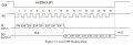
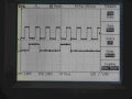
I also checked the BMP280 ALTIMETER D/S and the SPI SCL is also resting HIGH.
The READings from this look ok, so I'll leave [Define SPICLOCK_INVERT = 1 ]
C.
I tried: [ Define SPICLOCK_INVERT = 1 ]
No change to the error, the AK8963 is still not working properly.
I also checked the BMP280 ALTIMETER D/S and the SPI SCL is also resting HIGH.
The READings from this look ok, so I'll leave [Define SPICLOCK_INVERT = 1 ]
C.
Last edited: