Facebook
 Google
 GitHub
 Linkedin
Good Night,
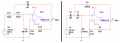
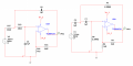
I have been trying to create 2 filters which I would cascade to make a basic band pass filter. I thought I understood the theory however it seems I do not. What I was trying to get on the output was a signal that would be filtered to only give a range of 0.5 - 5 Hz.
The input for this is a voltage that would be in micro amps after coming from a sensor then a current to voltage op - amp circuit. So the input voltage to this circuit would be uV. Attached would be diagrams of the circuits I was attempting to use.

On the left was supposed to be a 2nd order low pass filter and the right was the 2nd order high pass filter.
The equation used for the 0.5 Hz high pass filter:
\[ f=\frac{1}{2\pi RC} , C = 1 \mu, f = 0.5 Hz \\ R=\frac{1}{2\pi fC} =\frac{1}{2\pi *0.5*1\mu} =318309.89 \Omega \\ R\approx 320k\Omega \]
This equation would find the 2 input resistors as they were set to be equal.
The equation used for the 5 Hz low pass filter:
\[ f=\frac{1}{2\pi RC} , C = 1 \mu, f = 5 Hz \\ R=\frac{1}{2\pi fC} =\frac{1}{2\pi *5*1\mu} =31830.99 \Omega \\ R\approx 32k\Omega \]
This equation would find the 2 input resistors as they were set to be equal.
I am kind of lost as how to make it critically damped as I know the gain should not rise to more than 3 however in the pictures shown it was around there. These were just done to test please let me know how to better this.
This was done using multisim.
Thank you for your time,
- Sonny120
I have been trying to create 2 filters which I would cascade to make a basic band pass filter. I thought I understood the theory however it seems I do not. What I was trying to get on the output was a signal that would be filtered to only give a range of 0.5 - 5 Hz.
The input for this is a voltage that would be in micro amps after coming from a sensor then a current to voltage op - amp circuit. So the input voltage to this circuit would be uV. Attached would be diagrams of the circuits I was attempting to use.
On the left was supposed to be a 2nd order low pass filter and the right was the 2nd order high pass filter.
The equation used for the 0.5 Hz high pass filter:
\[ f=\frac{1}{2\pi RC} , C = 1 \mu, f = 0.5 Hz \\ R=\frac{1}{2\pi fC} =\frac{1}{2\pi *0.5*1\mu} =318309.89 \Omega \\ R\approx 320k\Omega \]
This equation would find the 2 input resistors as they were set to be equal.
The equation used for the 5 Hz low pass filter:
\[ f=\frac{1}{2\pi RC} , C = 1 \mu, f = 5 Hz \\ R=\frac{1}{2\pi fC} =\frac{1}{2\pi *5*1\mu} =31830.99 \Omega \\ R\approx 32k\Omega \]
This equation would find the 2 input resistors as they were set to be equal.
I am kind of lost as how to make it critically damped as I know the gain should not rise to more than 3 however in the pictures shown it was around there. These were just done to test please let me know how to better this.
This was done using multisim.
Thank you for your time,
- Sonny120
Attachments
-
 40.5 KB Views: 3