Filter roll off rate

Thread Starter

Homebrew1964

Joined Nov 22, 2024
192
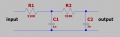
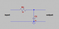
I was just experimenting with filters and built the first order Low pass one in the schematic, it works as expected reducing the amplitude of the waveform from
5V p-p to 3V p-p over a frequency range of 150kHz...is there a way to get a steeper roll off so i can get say the same reduction in waveform over 50kHz or do i need a different type of filter?
 

Attachments

AnalogKid

Joined Aug 1, 2013
12,130
In Electrical Engineering, filters are a huge topic of mathematics and circuit design. As above, a steeper rolloff requires more stages. But those stages can interact with each other to either enhance or degrade the overall filter performance. And you can get into more subtle effects - Compared to the simple Butterworth filter, a Bessel filter has a much "rounder" transition from the flat response frequencies to the attenuated frequencies; but it also has much better group delay and "phase response".

Deep down filter design involves poles, zeros, Laplace transforms, and things like gyrators. And complex numbers. The innergoogle is full of sites, from pre-programmed calculators and cookbooks to some of the scariest math in the discipline; some of it dating back to the 1800's, decades before the invention of the vacuum tube.

I'm not trying to scare you off; I think this is fascinating stuff and I'm still learning. Welcome to the party.

https://en.wikipedia.org/wiki/Butterworth_filter

ak
 

Jon Chandler

Joined Jun 12, 2008
1,596
So I can't create an illustration as fast as others ;)

Things you need to know about filters:

The cutoff frequency is:

f = 1/(2πRC) where

f = frequency in Hz

R = resistance in Ohms

C = capacitance in Farads

At the cutoff frequency, the level will be reduced by 3dB.

The SLOPE of the filter depends on the number of poles. For a simple RC filter, the slope is 6dB per octave or 20dB per decade.

If you question my filter knowledge, feel free to consult my patent, below.


single pole filter response.jpg
 

Attachments

Papabravo

Joined Feb 24, 2006
22,082
In exchange for allowing a controlled amount of ripple in the passband, a Chebyshev filter has a steeper rollof for a given order.
 

Thread Starter

Homebrew1964

Joined Nov 22, 2024
192
ok i built the 2nd order low pass RC filter and.....HUGE difference compared to the 1st order one from yesterday, very steep roll off in comparison.

I'm finding my journey into the world of electronics very exciting :D
 

Attachments

ericgibbs

Joined Jan 29, 2010
21,442
hi Hb,
I see that you are using LTSpice to draw your RC circuit.
I realise you are still learning LTS, but I thought you would like to see your circuit being simulated.
If you need any explanation, just ask.
E
EEG 2103.jpgEG 2104.jpg
 

Attachments

LvW

Joined Jun 13, 2013
2,027
In exchange for allowing a controlled amount of ripple in the passband, a Chebyshev filter has a steeper rollof for a given order.
Steeper rollof than....?
I think, the rollof - that is the slope of the magnitude far above the pole frequency - is determined by the order of the transfer function only (as demonstrated in post#2), independent on the approximation (Butterworth, Chebyshev, Thomson-Bessel,...).
However, in comparison to a Butterworth response, the Chebyshev response provides more attenuation in the small transition region between the passband and the stopband.
 
Last edited:

Thread Starter

Homebrew1964

Joined Nov 22, 2024
192
hi Hb,
I see that you are using LTSpice to draw your RC circuit.
I realise you are still learning LTS, but I thought you would like to see your circuit being simulated.
If you need any explanation, just ask.
E
EView attachment 367339View attachment 367340
Thanks very much Eric, interesting to see the result of my filter in a graph, i havn't got to doing simulations yet, i am still assembling and testing on breadboard.

thanks again.
 

Papabravo

Joined Feb 24, 2006
22,082
Steeper rollof than....?
I think, the rollof - that is the slope of the magnitude far above the pole frequency - is determined by the order of the transfer function only (as demonstrated in post#2), independent on the approximation (Butterworth, Chebyshev, Thomson-Bessel,...).
However, in comparison to a Butterworth response, the Chebyshev response provides more attenuation in the small transition region between the passband and the stopband.
Steeper rollof than....? Butterworth
 

Marley

Joined Apr 4, 2016
519
The Elliptic filter has the fastest roll-off rate. You can't get something for nothing however and the downside is ripple in the passband and stopband and "group delay" that depends on frequency.
In my 20's used to work with an aged engineer (probably as old as I am now) who was a wizard at designing these things. He knew the maths and could write down a scary equation just like that but cheated and had a large book which had examples of all sorts of filters with "normalised" values (impedance = 1Ω, frequency = 1ω (1 radian/sec)) and you could scale the component values to suit your application. Now we have computers, of course - easy!
It is a very interesting subject - real engineering - and I'm not clever enough to have really got deep into it.
Some say: "Oh it can all be done digitally now." But the same rules of physics apply - digital or analog.
 

LvW

Joined Jun 13, 2013
2,027
The Elliptic filter has the fastest roll-off rate. You can't get something for nothing however and the downside is ripple in the passband and stopband and "group delay" that depends on frequency.
Yes - and the same applies to the "inverse Chebyshev" approxination also, however, without any ripple in the passband.
But the design process (and tuning) is more complicated in comparison to all the "Allpol-Filter" approximations.
This is due to the real zeroes of the magnitude response.
 

crutschow

Joined Mar 14, 2008
38,508
To be clear, to get the sharper rolloff at the corner frequency that you get from Butterworth, Chebyshev, Thomson-Bessel, Elliptic, etc. filter types you need to go to RC active-filters with a gain element (typically an op amp) or LC filters.
 

Marley

Joined Apr 4, 2016
519
To be clear, to get the sharper rolloff at the corner frequency that you get from Butterworth, Chebyshev, Thomson-Bessel, Elliptic, etc. filter types you need to go to RC active-filters with a gain element (typically an op amp) or LC filters.
Back in the day (where I was working) it was just L's and C's working at audio frequencies (telephone line modems). The beauty of that was the filters were bi-directional and could have signals going both ways - simultaneously!

We did move into active filters using op-amps a little later and as the aged engineer remarked - op-amps (back then anyway) were not as good as you think they are. Open loop phase shifts at only units of hertz.
 

crutschow

Joined Mar 14, 2008
38,508
Open loop phase shifts at only units of hertz.
All op amps have that due to their internal 1-pole rolloff starting at a low frequency, so that their closed-loop response is stable.
It has little effect on a active-filter's closed-loop phase-shift at frequencies well below the op amp's gain-bandwidth value (which is normally were you want to be).
 
Top