 Facebook
 Google
 GitHub
 Linkedin

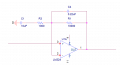
I would appreciate some help understanding this circuit.
Am I correct in saying that R1 and C2 constitute a low pass filter and C1 and R3 are a high pass filter? struggling to comprehend whats going on, oi know its a band pass I have simulated the circuit with a 0.5V AC 1-10kHz testbench, here are the results

I got these values using 1/2*pi*RC for what I thought were the low and high pass filter, I need a low pass fc of 15Hz and a high pass of 75Hz with 11 gain, I know the gain is correct but can someone show me how to calculate the filter specs?
The cursors show the -3dB points and they are nowhere near what I expected, any help appreciated!
EDIT: I know the high pass before is there, ive calculated this previously

Attachments
-
 11.3 KB Views: 3
 -
 100.5 KB Views: 6


