Fender Mini Deluxe Amp

Thread Starter

Jsprite7660

Joined Jan 9, 2024
48
Hey all,

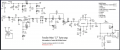
I'm currently fixing an amp for repair practice and am stuck on finding what I believe is a short circuit somewhere. I could care less about the actual amp and am doing this for the learning experience. It's a Fender Mini '57 Twin. Attached is a photo of the schematic that someone drew out and uploaded, as there weren't originals we could find.

The problem; I see 9VDC at the power input jack but once the switch is turned on, the power goes down to .5 VDC and a faint ticking noise is heard on the speakers.

I have;

-Replaced BOTH of the IC's and tested them and can see no shorts to ground on the pins of either IC. The ground terminals test continuity to ground

-Tested all capacitors which all read in the ballpark and none showed continuity
-Tested all of the resistors and saw good numbers and no continuity
-Removed the power switch, as process of elimination, and hardwired it. Same result
-removed the female power jack and hardwired that, just to see. Same result
-replaced the D3 Diode.
-Made sure all ground points read correct continuity
-Tested the other two diodes and read good
-Also looked for bridging and found none between points on PCB
-Tested all pots and their ground connections


Any suggestions?
 

Attachments

MrChips

Joined Oct 2, 2009
35,030
That is not how I would approach the problem. I do not go replacing components willy nilly.

9 VDC power in drops to 0.5 VDC once switch is turned on.
Firstly, determine what value load resistance on the power input would cause the voltage to drop.
This will tell you the current capability of the power supply. This will also tell you if the power supply is good or not.

Next, after determining that the power supply is good, find what is loading down the power supply.
Do this by removing loads on the power supply. Eventually you are bound to find the culprit.
 

wayneh

Joined Sep 9, 2010
18,135
I suggest posting some pictures of your PCB. Maybe someone will have ideas from seeing that.

How confident are you in the "bootleg" schematic? Does it seem to match up with what you're seeing?

Do you have an oscilloscope and a tone generator? You should be able to trace the signal.
 

Thread Starter

Jsprite7660

Joined Jan 9, 2024
48
I suggest posting some pictures of your PCB. Maybe someone will have ideas from seeing that.

How confident are you in the "bootleg" schematic? Does it seem to match up with what you're seeing?

Do you have an oscilloscope and a tone generator? You should be able to trace the signal.
Yes, the schematic matches exactly to the PCB.
 

Thread Starter

Jsprite7660

Joined Jan 9, 2024
48
That is not how I would approach the problem. I do not go replacing components willy nilly.

9 VDC power in drops to 0.5 VDC once switch is turned on.
Firstly, determine what value load resistance on the power input would cause the voltage to drop.
This will tell you the current capability of the power supply. This will also tell you if the power supply is good or not.

Next, after determining that the power supply is good, find what is loading down the power supply.
Do this by removing loads on the power supply. Eventually you are bound to find the culprit.
The power supply is good
 
My first thought is that someone used a power supply of the wrong polarity and smoked the diode or the input cap (D3, C19). You don't say if the LED is on or not. Also, insert a 1/4 plug into the headphone jack that is not connected to anything (open up the output) to see if the behavior changes and measure at that jack for DC.
 

Thread Starter

Jsprite7660

Joined Jan 9, 2024
48
After removing a few loads and testing I came to the diode. The 9VDC returns with the diode removed.

The diode was brand new tho and still tests fine on the multimeter. Before ordering a new one, is there any other recommendations to be sure this is the culprit?
 

Thread Starter

Jsprite7660

Joined Jan 9, 2024
48
Oh man......you guys are gonna get a good laugh out of this.

Before getting to the diode, the IC's were already out as well as C14 and C17. ( was checking their capacitance out of circuit)

So then I get to the diode, as I mentioned, and see the voltage return with it removed. And yes the polarity was correct I obsessively checked.

So I put the IC's back in and turned it on without the diode to see but ALSO without C14 and C17.

The Amp Worked. (Past tense) It worked for like 3 seconds(heard sound from my 1/4 which had a keyboard sustained note) and I realized I left the caps out! but the output IC fried before I could turn it off. It was extremely hot.

So that's a big shame on me. My questions tho;

Why and how did it work without the diode in?

And the output IC fried because those caps couple it to ground correct? So the current had nowhere to flow(Even tho there's another ground terminal which was connected)
 

MrChips

Joined Oct 2, 2009
35,030
Your analysis is flawed.
@abrsvc said it first in post #7.
What likely happened is someone applied power of the wrong polarity. This blew D3 into short circuit mode.
Then the replacement D3 was inserted backwards. This created a short circuit across the power input, overloading the power input.

D3 is not needed for the circuit to work. It is there for protection against reverse input polarity.

Why the power IC blew is a different story. Possibly, it went into oscillation mode.

Proper trouble shooting procedure is not hit and miss. It requires an understanding of the function of each component in the circuit. If you do not have this knowledge but still wish to repair your own electronics, it would be best to come here first where we can guide you step by step.
 
I've been fixing stuff like this for more years that I care to admit here... I sometimes feel like Carnak(sp?).
For simple amp circuits like here, the problem is usually the output IC, but with it changed and the voltage drop, it is a classic polarity/protection issue. Seen this with laptops too.
 

Thread Starter

Jsprite7660

Joined Jan 9, 2024
48
Well I got another power IC on the way and can jump back in line with it. Thanks for the help. The diode definitely was not flipped. I'm not that much of a bozo. triple....no checked it at least 10 times.

Will be back when IC arrives to re-evaluate
 

MrChips

Joined Oct 2, 2009
35,030
As @abrsvc said in post #7, insert a plug with no connection into the headphone jack.
The purpose if this is to disconnect the speaker load on the output of the amp. Of course, you will not know if the amp is back to working.

Make sure the missing capacitors are back in place.
With no input source, you want to measure the voltage on pin 6 of the KIA6213 amplifier IC (at the positive leg of C18). It should be about 4.5 V.

Before connecting back to the speakers, check that C18 is not shorting. If it is shorting, the IC will blow again.
 

Thread Starter

Jsprite7660

Joined Jan 9, 2024
48
As @abrsvc said in post #7, insert a plug with no connection into the headphone jack.
The purpose if this is to disconnect the speaker load on the output of the amp. Of course, you will not know if the amp is back to working.

Make sure the missing capacitors are back in place.
With no input source, you want to measure the voltage on pin 6 of the KIA6213 amplifier IC (at the positive leg of C18). It should be about 4.5 V.

Before connecting back to the speakers, check that C18 is not shorting. If it is shorting, the IC will blow again.
Ok thank you, will do. I'll check back after I get it back up and ready to test.

Thanks
 
Top