 Facebook
 Google
 GitHub
 Linkedin
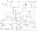
Hi, the power supply of my samsung TV doesn't work anymore and I'd like to understand the way it works.
I don't get how the SPC7011F gets a stable output voltage as I find a positive feedback.
Can someone tell me what's wrong with the following rationale ?
Here it is:
Vo voltage is controlled via the FB pin.
It is said that when the rising voltage ramp on non inverting terminal of the PWM comparator becomes greater
than voltage on inverting terminal of PWM comparator, Q1 mosfet isn't conducting anymore.
Thus the output capacitor gets loaded through D1 diode
Over a cycle, the output capacitor can only charge when Q1 is not conducting, and the less Q1 is conducting, the more the voltage Vo increases.
If Vo increases, the voltage Vfb on the FB pin increases.
When Vfb increases, the output of ERRAMP decreases, Vfb being on the inverting terminal of the ERRAMP amplifier.
And when the ERRAMP output voltage decreases, then the PWM comparator output will go high earlier in the cycle, so mosfet Q1 will be off earlier in the cycle and the output capacitor will charge earlier and therefore for longer duration in the cycle, which will increase Vo again.
This seems like positive feedback ...
Thanks for your help,
Cédric
Attachments
-
 47.8 KB Views: 9
 -
744.7 KB Views: 4


