Feedback for LF parasitic oscillations (ARRL Handbook)

Thread Starter

Elerion

Joined Sep 11, 2017
125
Hi everyone.

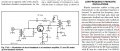
This comes from 2008 and 2011 editions (probably, others too); a shunt-shunt feedback topology is recommended to deal with low frequency oscillations in bipolar RF power amplifier stages, due to high current gain at low frequencies.

The text states: "negative feedback [...] increases progressively as the frequency is lowered".
I'd say the opposite. Reactance of C1 gets higher as freq decreases, so I'd say that negative feedback decreases too.
An open circuit at C1 breaks the feedback loop (max gain).
A short circuit at C1 gets maximum feedback (lower gain).

Can anyone point me where I'm wrong?
Thanks.
 

Attachments

Thread Starter

Elerion

Joined Sep 11, 2017
125
Isn't it strange? That same information has been published several times (on several editions, and it is a very popular book), and I've seen no errata list pointing to it.
Could it be interpreted?
How could negative feedback help stabilize the circuit?
 

MrAl

Joined Jun 17, 2014
11,474
Hello,

Negative feedback often helps stabilize the gain to keep it at a certain level.
Dynamic feedback however is frequency sensitive and therefore makes the amplifier behave differently at different frequencies.

To get lower gain at lower frequencies using capacitance however requires some capacitance in series, not in parallel, and not in the negative feedback loop but possibly in the positive feedback loop if there is one. This amplifier does not appear to have the right feedback and so the gain will decrease with increasing frequency.
 

Thread Starter

Elerion

Joined Sep 11, 2017
125
The schematic and similar text is found in editions that are two decades older.
If there's something wrong with it, they have been publising it for maybe 30 years...
 

MrAl

Joined Jun 17, 2014
11,474
The schematic and similar text is found in editions that are two decades older.
If there's something wrong with it, they have been publising it for maybe 30 years...
Hi,

Yes that's is a shame. But then again the name does not start with "Amateur" for nothing :)

I tried to figure out if they swapped numbers or something but nothing turned up reasonable.

As it turns out though, the resistor R2 and capacitor C2 do act in the right way. The cap shunts R2 for high frequencies thus increasing the gain, while as the frequency gets lower R2 has more effect just reducing gain. So the negative feedback is probably for limiting the high end frequencies they just did not describe it correctly i guess.

You should show the entire writeup as that may explain this other action.
 
Last edited:

Thread Starter

Elerion

Joined Sep 11, 2017
125
You should show the entire writeup as that may explain this other action.
I'd say this: the emitter degeneration lowers the gain at low frequencies, which seem to be the desired effect. But it also raises input impedance, causing mismatch, so the shunt feedback is added to counteract this, or balance it somehow.
Obviously (?), at very low frequencies, emitter degeneration is at its maximum, but shunt feedback has dissapeared completely, so the input Z is unbearable, and should be handled by diplexer or someother mean.
Still, I don't fully get the point, and don't think it is clearly explained.

Any bet out there?
 

Attachments

Top