Feedback amplifier Working Not understood

Thread Starter

Nitish2506

Joined Mar 30, 2020
7
Hi

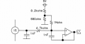
I was studying some how to interface O2 Sensor to micro controller. I got some reference connections diagram. I want to understand amplifier type in circuit & reason of using capacitor in feedback loop. Please help me to understand this.
 

Attachments

danadak

Joined Mar 10, 2018
4,057
The cap in sim alters the freq at which the response peaks. And affects the
BW olf the response.

Basic response of circuit looks like -

1585573878608.png


With 1 pF fdbk cap looks like -


1585573927350.png

Intuitively the cap at low freq is irrelevant because OpAmp establishes a virtual ground
across it. But as OpASmp runs out of G at higher freq, and its Zout rises, cap feed forwards
signal bypassing OpAmp. Seems like an "odd" topology.....


Regards, Dana.
 
Last edited:

LvW

Joined Jun 13, 2013
1,752
Hi nitish2506.......it is the task of the cap between both opamp input nodes to improve (or even to ensure) the stability of the unity-gain amplifier. Unity-gain configuration (100% feedback) is the most critical configuration as far as stability against oscillation is concerned.
This capacitor does not influence the closed-loop gain of the amplifier but it remarkably reduces the loop gain for rising frequencies (and with it the closed-loop bandwidth) and, hence, improves the stability margin. That means, in the time domain the pulse response will be improved (less overshoot).

Explanation: The cap allows a certain percentage of positive feedback and, hence, reduces full negative feedback - resulting in less loop gain.

(Comment to danadak´s answer: Gain deep in the negative dB region???)
 

DickCappels

Joined Aug 21, 2008
10,152
Shunting the inputs it would also raise the noise gain, which is sometimes an acceptable trade-off for the stability that can come from lowering the loop gain.
 

danadak

Joined Mar 10, 2018
4,057
I had an error in sim wiring, so I edited the AC bode post #2 above to correct.

Also transient response edited in post #4. Not much evidence phase margin impacted....
Probably because of the dominant compensation internal to the LM324 I used in sim.

Funny thing is the bode plot shows impact on phase margin, but transient time domain
does not. Maybe fact I had to use current source because of large input cap to circuit,
and everything just gets integrated.....

Regards, Dana.
 
Last edited:
Top