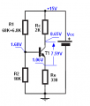
Everything is the same, but the calculations don't match the actual measurements???

Thread Starter

rougie

Joined Dec 11, 2006
410
Okay,

I had some spare time today and I have experimented with transistors step by step to make sure I understand most details as possible.

I know Beta is different from transistor to transistor, I know resistors have tolerances, I know power supplies can be a little off, I know temperature affects the transistor hFE and I understand that we would use a resistor feedback biasing configuration instead of the circuit shown but this is ridiculous !!!!!

Please consider the video at:

http://www.youtube.com/watch?v=nSwq6TO6mTE

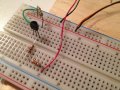
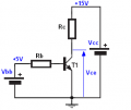
Please view the exact same circuit in my attachment. The beta of *my* transistor is 104 at 24.4 degrees celcius. The transistor's temperature has been measured with an infra-red thermometer.

I have 2-1k ohm resistors in series which sum up to exactly 1.983k ohms as Rc. My Rb is exactly 99300 ohms. The power supplies are exactly 5.02VDC (Red and black wires) and 15.05VDC (orange and black wire). And the actual measured Vbe is 0.569 VDC for this transistor.

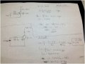
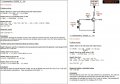
I have done the calculations as per video (see top part of my diagram attachment) and then I have re-done the calculations with the exact values in respect to my on board components (please view the bottom part of my diagram attachment). Now I understand that the video comes up with a Vce of 6.4VDC. I have re-done the calculations with the exact values of my components at the bottom part of my attachment and I calculate Vce as 5.79VDC! And this is understandable when considering all the variations of tolerances of each component. HOWEVER......

Why do I measure a Vce of 2.92 VDC ???????

I understand that the components may vary... BUT NOT BY THAT MUCH???

I could tolerate with a measured Vce of 5.0, 5.3, 5.8, 6.1, 6.9 or even 7.3 for heaven's sakes........ BUT 2.92VDC !!!!!!!!!!!!

Something is totally off here... this is not a variation problem due to different betas or component tolerances ... this is as if something is totally disconnected or dis-functional!!! I re-checked my circuit a dozen times... made sure all my voltages are correct... and so forth...

Does anyone see what I am doing wrong ! And why is Vce soooo off from the calculations!!!!

This is beyond being discouraged... this is almost being upset :mad:

All help really appreciated!
r
 

Attachments

Jony130

Joined Feb 17, 2009
5,598
The answer is simple your BJT has a actually a large BETA then 104.
Ic = (15 - 2.92V)/2K = 6mA
Ib = (5 - 0.569)/100K = 44.31μA
so the β = 6mA/44.31μA = 135

Tomorrow I try repeat your experiment. I will measure the BETA by using multimeter Hfe function.
And my multimeter specified that hfe is for Ib = 10uA
 
Last edited:

Thread Starter

rougie

Joined Dec 11, 2006
410
Hi Jony130...

So then why is it that we measure a hFE of 104. Or let me re-phrase that:

Why is it that when I plug in my transistor in the HFE slot of my multimeter, it does not show 135 and shows 104 instead??

Is it that my multimeter that is badly calibrated...?
Is it that beta changes when the transistor is connected to the circuit...?

There has to be some explanation.... this is driving me up a wall!!!!


And my multimeter specified that hfe is for Ib = 10uA
So does mine.. so you will definitely experience the same issue I have!

Here is what mine says:

The LCD will read approximate hFE values based on the test condition of the
10 µA DC base current and Vce of approximately 1.5 V DC.
So what are we suppose to make of this anyways..... in the circuit, our base current is approx. 43ua!!! So based on this how can our meters be of any use for measuring the beta of a transistor..... ?


thanks for your reply!
r
 
Last edited:

Jony130

Joined Feb 17, 2009
5,598
Why is it that when I plug in my transistor in the HFE slot of my multimeter, it does not show 135 and shows 104 instead??
In your multimeter Ib has a different value than in the actual circuit.

Is it that my multimeter that is badly calibrated...?
I don't think so.

Is it that beta changes when the transistor is connected to the circuit...?

There has to be some explanation.... this is driving me up a wall!!!!
Yes the answer lies in figure 3
http://www.onsemi.com/pub_link/Collateral/PN2222-D.PDF
 

Thread Starter

rougie

Joined Dec 11, 2006
410
Hi Jony130,

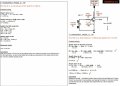
Is this what you mean ... see attachment.....

If so, sorry for being such a stick in the mud lol! But it still doesn't make sense as the graph supposes that the HFE is approximately 180... and that makes no sense since according to calculations it gives an RC drop of 15.9 VDC ???? which is even greater that the 15VDC rails ???

confused...

Something tells me I should of stayed in bed today LOL!

thanks for your help!
r
 

Attachments

Jony130

Joined Feb 17, 2009
5,598
Is this what you mean ... see attachment.....

If so, sorry for being such a stick in the mud lol! But it still doesn't make sense as the graph supposes that the HFE is approximately 180... and that makes no sense since according to calculations it gives an RC drop of 15.9 VDC ???? which is even greater that the 15VDC rails ???
I want you to see that hfe is not a constant value, but hfe it is a current dependent. Also this graph show a typical values not a actual value.
And typical value can vary. How much? I don''t know,maybe by ±30% or so.
Something tells me I should of stayed in bed today LOL!
Maybe you should. But I now I need to go to sleep.
 

Thread Starter

rougie

Joined Dec 11, 2006
410
I want you to see that hfe is not a constant value, but hfe it is a current dependent. Also this graph show a typical values not a actual value.
And typical value can vary. How much? I don''t know,maybe by ±30% or so.
still, the volatility is unbelievable !!! it's really amazing how beta
is really not dependable, but in many tutorials, very much
so depend on a beta value in their calculations....

well, Thank you for your help!
and sleep well!!
r
 
Last edited:

Thread Starter

rougie

Joined Dec 11, 2006
410
You may have collector and emitter reversed.
humm! I don't think so.... I mean you can clearly see in my
circuit that the emitter and collector are correctly connected!!!

anyhow... I'll live with it!

thanks
r
 

Audioguru

Joined Dec 20, 2007
11,248
We design a transistor circuit so it works fine with ANY passing value of beta.
This extremely simple circuit does not.

The hFE socket on a multimeter is not designed to read the actual beta since its current is very low but instead is used to measure and select MATCHING transistors that have the same amount of hFE.
 

t_n_k

Joined Mar 6, 2009
5,455
I wouldn't worry - Audioguru has clarified my doubts. Pinout conventions vary I know - I'm more accustomed to the European convention.
 

Sensacell

Joined Jun 19, 2012
3,787
The fact that Beta varies all over the place really freaked me out when I started working with transistors, textbooks seldom mention this fact, experiments don't work out and one gets frustrated.

The equations should have disclaimers- just like cups of hot coffee from Mcdonalds, or car mirrors.

"Warning: may not yield expected results"
"Beta in mirror may be larger than it appears to be"
 

Jony130

Joined Feb 17, 2009
5,598
I also did some measurement.
I pick BJT BC337-25 (I live in Europe so I use European BJT's).
The datasheet show for BC337-25 Hfe_min = 160 and typical hfe close to 250.

I use the same diagram as you.


The multimeter show hfe = 265 for Ib = 10μA and Vce = 2.6V
And first what I do was to assume that I want Vce = 7.5V with Rc = 2K.
So we need Ic = 7.5V/2K = 3.75mA and Ib = 3.75mA/265 = 14.1μA
So I need Rb = (Vbb - Vbe)/Ib = (5V - 0.6V)/14.1μA = 312KΩ and I pick Rb = 330KΩ

So for Rc = 2K and Rb = 330KΩ I measure Vce = 7.9V (instead 7.5V).
But Hfe was close to the value that was show by multimeter Ic/Ib = 3.55mV/13.6uA = 261 This is because Ib was close to multimeter Ib test current.
The next thing I did was changing Rb resistor to Rb = 100K , I increase the base current to Ib = 44μA. I also need to change Rc to 620Ω.
So now we expect that for Rb = 100KΩ; Rc = 620Ω; hfe = 265 we get:
Ic = 11.66mA and Vce = 7.8V
But in the real circuit I measure Ic = 13.53mA and Vce = 6.6V
And this means that actual circuit hfe for Ib = 44μA is greater than hfe = 265.
Hfe = 13.53mA/44μA = 307

And this is why we don't use this circuit as a voltage amplifier.
We use it only as a switch when we don't care about hfe actual value.
 

Attachments

Thread Starter

rougie

Joined Dec 11, 2006
410
The equations should have disclaimers- just like cups of hot coffee from Mcdonalds, or car mirrors.

"Warning: may not yield expected results"
"Beta in mirror may be larger than it appears to be"
hahaha!

Or perhaps call up Fairchild or Vishay or whoever else makes these things and tell them:

"Hey guys! how about making your beta a little more stable,
beginners like me would like that! " :D :D :D

cheers!
r
 

Thread Starter

rougie

Joined Dec 11, 2006
410
Hello Jony130,

I have read your example circuit and I have re-done my circuit too and for the first time I can say I enjoy electronics! :)

Through calculations and a little bit of circuit investigation with my multi-meter I was able to say that the physical circuit finally matches the theory!

To all whom teach and write tutorials on the Internet about electronics... I would like to share my thoughts with you!

You see... most competent electronics fellows don't recall the gray zones when they were first exposed to transistors. This is no ones fault as this is human nature to forget some of the quirks that led you to understand a subject. Rest assure this happens in any field. That being said and done... when I was first exposed to the tutorial link:

http://www.allaboutcircuits.com/vol_3/chpt_4/10.html

there are some important quirks that must be addressed here....

What would happen is I would create a physical circuit on my work bench and based on the calculations shown in the link above I was getting totally wrong values on my multi-meter. At this point telling a newbie repeatedly that the beta of a transistor might not be 100 or 150 or 78 is pretty confusing and redundant.

When I built my first circuit and no measured readings matched the calculated values guess what goes on in a newbie's mind at that very moment. Well, at this very moment a newbie wonders what calculations are required to come up to the measurements I have NOW!!! In other words, what one calculates is what one wishes to see!

In the attachments below I have done 2 examples. The first one has the way a simple circuit like this one should be rationalized. And the 2nd example has the actual methods to get to the intended values base on the rationalizations accomplished in the 1st example.

In example #1, I assumed that the beta was 104 because my meter told me so. Even though that value was wrong, it was a starting point. When I saw that the calculated Vce of 6.01VDC was not correct and that a Vce of 2.92VDC was measured instead, Jony130 taught me that we at least have a true value which was 2.92 for Vce. Thanks Jony130!

From this true Vce of 2.92VDC I was able to get the true Ic, Ib and beta and was able to understand why Vce was 2.92VDC .... :) hence again:

"what one calculates is what one wishes to see"

humm I might use that as my signature !!!! LOL

Aaaaaaaanyways.... If anyone wants to view the two attachments below of how I rationalized this simple circuit then go ahead.

I am very happy that I can finally calculate something and actually measure the same values in a circuit on my bench!

Jony130, you have helped me alot and I thank you very much...

There's ooooooooooooone little incy wincy little thing that is still bothering me......

In reference to our multi-meters here.....

I find it weird that a multi-meter is able to shoot out a Beta value by introducing 10ua through the base of a transistor at a Vce of 1.5VDC BUT in no way can we use that beta value in relation to that figure #3 from the PN2222 spec sheet we discussed earlier!!!!!

Like, I mean, If my meter says that this transistor has a beta of 104 when biased with a 10ua at 1.5Vce parameters, isn't there a way to convert that very accurate beta (under its biasing circumstance) to match a beta on the current gain map of figure #3 of the PN2222 data sheet?

Let me take stab in the dark on this one.... if my meter says beta = 104 when biased with 10ua AND if I multiply that by 104 I get 1.04 ma which puts it as a legible value on the x axis of figure #3 of PN2222 datasheet. Tracing it up to the y axis, it pretty well gives the correct value of the gain which seems to be about 135!!!!!!

I may be terribly wrong here... this is just an idea I am throwing out here......

Okay, well, tomorrow I will do the same experiment with voltage divider bias.... and definitely let you all know of any problems that may come up ... :)

I thank all the fellows who have helped, supported and contributed to my threads regarding transistors.

regards
r
 

Attachments

Last edited:

t_n_k

Joined Mar 6, 2009
5,455
I think your conversion method "worked" by virtue of the typical underlying HFE value for the curves shown in figure 3.

Looking more carefully at the curves in figure 3 for the case of Vce at 1V [solid line] and 10V [dashed line] at 25°C, the spread in HFE value isn't as great as a factor of ~135:104. At 1mA say, the spread appears to be roughly 140 to 160 with Vce going from 1V to 10V.

So while Vce does have an influence [due to the Early Effect] the greater direct dependence on the Ic value is the significant factor.
 

Jony130

Joined Feb 17, 2009
5,598
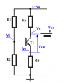
Ok lets design bias network for this circuit


I assume Rc<< Rload so I pick Rc = 2KΩ and also Ve = 1V ; Vce = 7.5V

So for Rc = 1K and Vce = 7.5K we have
Ic = Ie = (Vcc - Vce - Ve)/Rc = 3.25mA
And
Re = 1V/2.95mA = 307Ω = 330Ω

Because I chose Re 330Ω Ve voltage will be higher then 1V
New Ve = 3.25mA * 330Ω = 1.07V

Vb = Ve + Vbe = 1.73V

And the BJT I will going to use is BC337-25 with hfe_min=160
Ib_max = Ic/hfe = 20μA.
So
R2 = Vb/(10*Ib) = 8.65KΩ = 8.2KΩ but it is hard to get this resistor value so I change R2 to 10KΩ.
So the new voltage divider current is equal to
Id = 1.73V/10K = 173μA
And now we can select R1
R1 = (Vcc - Vb)/Id = 75KΩ

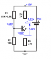
Now it is time to show some real world measurement.
The first one is for BC337-25

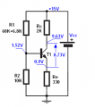
And after I change BJT which has Hfe_min = 250 BC337-40


And now let's see what will happen when BJT has a smaller Hfe than we assumed. I assume Hfe_min = 160 but I put BD139-10 with Hfe_min = 63;


This measurement clearly show that voltage divider circuit + Re resistor bias circuit is far more immune for hfe change than circuit we analysis in previous post.
 

Attachments

Last edited:
Top