Facebook
 Google
 GitHub
 Linkedin
Hi.
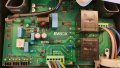
I got my hands on a new but faulty EVBOX charger (3 phase charger for an electric car) and would appreciate any help in finding the source of the problem.
When the charger is plugged into the mains (3phase 230VAC + N + PE) it goes into fault mode indicated by a red light.
When I measure the voltages on the main connections I get the following result:
L1-L2: 412V
L2-L3: 412V
L3-L1: 412V
L1-N: 236V
L2-N: 236V
L3-N: 239V
L1-PE: 93V
L2-PE: 156V
L3-PE: 146V
PE-N: 63V
There is clearly something wrong with the device as:
phase to PE reads between 93 and 156V (should be around 230V)
PE to N reads 63V (Should be close to 0V)
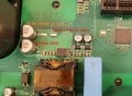
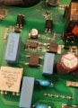
I tried to desolder the blue tyristors and the grey surgearrester on the right of the main supply thinking these could be leaking to gruond. This had no effect.
L1 is used to power the DC circuits (control and protection part of the CB).
This leads me to think that there is some problem with the inverter/rectifier part for L1.
I got my hands on a new but faulty EVBOX charger (3 phase charger for an electric car) and would appreciate any help in finding the source of the problem.
When the charger is plugged into the mains (3phase 230VAC + N + PE) it goes into fault mode indicated by a red light.
When I measure the voltages on the main connections I get the following result:
L1-L2: 412V
L2-L3: 412V
L3-L1: 412V
L1-N: 236V
L2-N: 236V
L3-N: 239V
L1-PE: 93V
L2-PE: 156V
L3-PE: 146V
PE-N: 63V
There is clearly something wrong with the device as:
phase to PE reads between 93 and 156V (should be around 230V)
PE to N reads 63V (Should be close to 0V)
I tried to desolder the blue tyristors and the grey surgearrester on the right of the main supply thinking these could be leaking to gruond. This had no effect.
L1 is used to power the DC circuits (control and protection part of the CB).
This leads me to think that there is some problem with the inverter/rectifier part for L1.
Attachments
-
 1,016.4 KB Views: 6
 -
 2.3 MB Views: 6
 -
 1.1 MB Views: 6
 -
 214.5 KB Views: 6