Facebook
 Google
 GitHub
 Linkedin
Good day folks!
It has been a while since my last visit in this forum, so hi to everyone I knew few years ago..
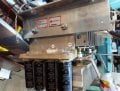
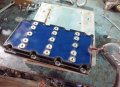
I've recently been given (as a gift, could not have been better") ) a MIG welder, Esab 502, internals..i.e. power transformer, and output diods+thyristors I believe)
) a MIG welder, Esab 502, internals..i.e. power transformer, and output diods+thyristors I believe)
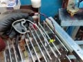
Please see the pictures attached.
I was hoping it had taps on primary side, but not. The control is done on secondary side.
There are black and red wires sticking out, I think these are for thyristor control. Also 2 grey one, I guess for thermo signal
Question is, can I drive this monster by just adding PWM based on 555, and 1 IRF540 (may not be even needed).?
Logic is to have thyristor open for period of time, which should control the volts and amps
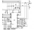
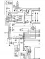
I've got the circuit diagram, but it does not show details, i.e. it just says "control board"
It has been a while since my last visit in this forum, so hi to everyone I knew few years ago..
I've recently been given (as a gift, could not have been better
) a MIG welder, Esab 502, internals..i.e. power transformer, and output diods+thyristors I believe)Please see the pictures attached.
I was hoping it had taps on primary side, but not. The control is done on secondary side.
There are black and red wires sticking out, I think these are for thyristor control. Also 2 grey one, I guess for thermo signal
Question is, can I drive this monster by just adding PWM based on 555, and 1 IRF540 (may not be even needed).?
Logic is to have thyristor open for period of time, which should control the volts and amps
I've got the circuit diagram, but it does not show details, i.e. it just says "control board"