Inverter welder repair

Thread Starter

Gizer

Joined Aug 15, 2017
52
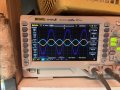
My inverter based welder has developed a fault and ive tried a couple of things but didnt manage to fix it.

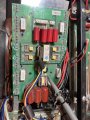
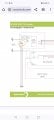
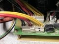
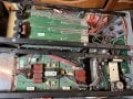
the pcb at the top had a capacitor with a hole in it, so i started off with changing all 4 capacitors.

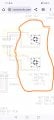
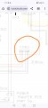
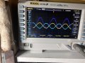
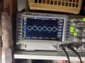
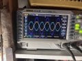
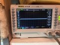
im pretty sure the fault is in tthis pcb. The rectifier/filter board below provides it 330v dc, but i read only 1v output from the board regardless of the welder settings which i change.

it either this board or the control circuitry giving the igbt’s timing signals.

so whats next in my debugging process?? Grateful for any tips as all!

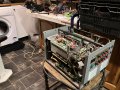
i can of course ship it off for fixing but i do want to learn to fix it if i can, i do have electrical/electronic experience, know safety precautions with the caps etc.
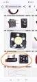
 

Attachments

Pyrex

Joined Feb 16, 2022
501
Hi
In most welders 330VDC is produced from 230VAC in a fairy simple way:
Mains 230VAC- starting resistor/relay- diode bridge- electrolytic capacitors.
So found those components and found a faulty one
 

Thread Starter

Gizer

Joined Aug 15, 2017
52
Hi Pyrex,
Thanks but i wasnt very clear in my post;
The rectifier is good, i read 330v dc coming into the switching pcb. Its the switching where the problemnis (i think), i dont get any ac/dc/pulse output from this board..

could also be the control circuitry but id guess the former is more likely.
 

Thread Starter

Gizer

Joined Aug 15, 2017
52
Any other thoughts? Appreciate and advice :oops: (even ditch it and buy a new one if this is too difficult to fix)
 

Pyrex

Joined Feb 16, 2022
501
Only today I found your answer. It's better to use the "quote" mode .

So, the issue is related to inverter . Found the pulse transformer (-s), the IGBT power modules or the IGBT power transistors are driven from those transformers. Check pulses on the primaries of those transformers, amplitude is about 15-20V, frequency is about 20-50kHz
 

Thread Starter

Gizer

Joined Aug 15, 2017
52
Only today I found your answer. It's better to use the "quote" mode .

So, the issue is related to inverter . Found the pulse transformer (-s), the IGBT power modules or the IGBT power transistors are driven from those transformers. Check pulses on the primaries of those transformers, amplitude is about 15-20V, frequency is about 20-50kHz
hi, thanks for the tip, i had a look around today and took some measurements with an oscilloscope;
so the board in the photo is where i found a blown capacitor and changed all 4 (bright red).
the rectifier brings dc to this board from the red/black wires you see in the photo. i'd previously read this using a multimeter. today with the scope, i saw that the dc is not smooth at all, its a sine wave with amplitude +330v / -8v, +340v/0v, at 50Hz. this puzzled me, i would have expected a much smoother dc input. i also played around with all the controls on the front and nothing really changed.

i thought the igbt transformer would be the one you can see in the pic with the scope leads attached. this measured around 180v also at 50hz. (not the levels you mentioned)

so overall, im a bit confused about what this pcb does??! could of course be that its not working correctly. there is another pcb bellow a large heat sink with transistors on, i guess that must be the switching/inverter board, but again, what is the purpose of this board?
 

Attachments

Pyrex

Joined Feb 16, 2022
501
I suppose the small pcb is the mosfet driver . Check all small resistors-10 Ohm or so- onboard. They tend to break.

If they are OK, check pulses with oscilloscope on the transformer's primary. The primary of the transformer is connected to two thick wires passed through the ferrite ring. Put probes on those two wires .
As I can see, there's 4x4 power Mosfets on the big PCB, each with individual resistors on the gates- yellow ,violet, gold , gold marked. Check those resistors onboard.
 

Thread Starter

Gizer

Joined Aug 15, 2017
52
I suppose the small pcb is the mosfet driver . Check all small resistors-10 Ohm or so- onboard. They tend to break.

If they are OK, check pulses with oscilloscope on the transformer's primary. The primary of the transformer is connected to two thick wires passed through the ferrite ring. Put probes on those two wires .
As I can see, there's 4x4 power Mosfets on the big PCB, each with individual resistors on the gates- yellow ,violet, gold , gold marked. Check those resistors onboard.
Thanks for the tips. So i checked the resistors across eachnof the mosfets, all seem ok (low reaiatance read and got continuity sound from dmm).

i checked the primary pulses (cables theu ferrite ring as you mentioned). It has an ac waveform, +\- 170 volts with a frequence of 50hz. Do these readings make sense? Other things i can check?

thanks
 

Pyrex

Joined Feb 16, 2022
501
I suspect something is wrong with the measurement technique.
330VDC voltage must be clean, without any 50Hz noise .
The voltage on the winding of the ferrite transformer must also be free of 50Hz noise .
Maybe you're connecting the oscilloscope to the wrong ground ?

I don't know what oscilloscope you're using, or if its case is insulated . If not insulated, be very careful when testing circuits tied to the mains. Mains voltage is deadly dangerous to the human !
 

Thread Starter

Gizer

Joined Aug 15, 2017
52
I suspect something is wrong with the measurement technique.
330VDC voltage must be clean, without any 50Hz noise .
The voltage on the winding of the ferrite transformer must also be free of 50Hz noise .
Maybe you're connecting the oscilloscope to the wrong ground ?

I don't know what oscilloscope you're using, or if its case is insulated . If not insulated, be very careful when testing circuits tied to the mains. Mains voltage is deadly dangerous to the human !
I was surprised to see the waveform too, since it looks like the rectifier has filter circuits. May well be my measurement, will have another look and try again.

Im using two 100x probes on the oscilloscope and the math function (poor mans differential probe).
reading mains directly with this set up, i see exaclty what youd expect (peak voltage, freq etc)
 

Thread Starter

Gizer

Joined Aug 15, 2017
52
I suspect something is wrong with the measurement technique.
330VDC voltage must be clean, without any 50Hz noise .
The voltage on the winding of the ferrite transformer must also be free of 50Hz noise .
Maybe you're connecting the oscilloscope to the wrong ground ?

I don't know what oscilloscope you're using, or if its case is insulated . If not insulated, be very careful when testing circuits tied to the mains. Mains voltage is deadly dangerous to the human !
I took more readings of this board and am even more confused now!

the input to this board from the rectifier looks like it AC waveform, see first image;

measuring the transformer, i also see a 50hz waveform, see other photos.

i have checked my measurements (taking difference in channel 1 and 2 using math function) with a staright mains ac reading, all seems fine with measurements and as expected.

i guess the rectifier isnt working? Take more readings of the rectifier/diodes etc??

Many thanks
 

Attachments

gaber2611

Joined Mar 14, 2013
321
What the model of this machine?, can you share the name plate?, so we may find schematic diagram or service manual?
Without scope, with only multimeter have you checked all the IGBTs and inverter part?, all ok?, or at least main components in inverter are OK?
 

Thread Starter

Gizer

Joined Aug 15, 2017
52
What the model of this machine?, can you share the name plate?, so we may find schematic diagram or service manual?
Without scope, with only multimeter have you checked all the IGBTs and inverter part?, all ok?, or at least main components in inverter are OK?
Its a Parweld Acdc tig 200
I will share manual i received from the company.

i havent checked all the inverter parts, will do so… there was one capacitor clearly burnt and i replaced all 4. Will check the igbts next.

but as mentioned, the input to the inverter from the rectifier looks v odd, basically a 240v ac waveform.. ???
 

gaber2611

Joined Mar 14, 2013
321
Its a Parweld Acdc tig 200
I will share manual i received from the company.

i havent checked all the inverter parts, will do so… there was one capacitor clearly burnt and i replaced all 4. Will check the igbts next.

but as mentioned, the input to the inverter from the rectifier looks v odd, basically a 240v ac waveform.. ???
[/QUOTE
No... Can only be AC at bridge input,
What the voltage on the positive and negative terminals of this bridge rectifier?, with multimeter, not with scope?, the black probe on bridge negative terminal, and the red probe on positive terminal of bridge, what is the DC voltage of multimeter?
The machine display any fault?
You say one from the big electrolytic Capacitor burned?, you mean exploded?
Please confirm
 

Attachments

gaber2611

Joined Mar 14, 2013
321
You should have 2 bridge rectification
At sockets number CON2 and CON4, have 308v dc?
You should be careful while take these measurements.
So I prefer take measurements without electricity plugged to machine, but if you looking for the input voltage to inverter, ive signed them from the manual
 

Attachments

Thread Starter

Gizer

Joined Aug 15, 2017
52
You should have 2 bridge rectification
At sockets number CON2 and CON4, have 308v dc?
You should be careful while take these measurements.
So I prefer take measurements without electricity plugged to machine, but if you looking for the input voltage to inverter, ive signed them from the manual
Thanks for your advice!

so i located the two bridge rectifiers and took readings from their inputs and outputs.

attached are the photos from the scope with two probes and math function (ch1-ch2, and ch2 inverted), so a differential probe of sorts.

if i measure mains, i would see a sine wave on ch1(live) and close to zero on the ch2(neutral).

here i am seeing sine wave on both channels on input and output of recifier. Strange no?

also, you mention taking measurements with power off. How is there a voltage if power is off? I did obeserve the sine wave! On one of the rectifiers, i did notice that the scope showed a sine wave when off but both lines went flat when powered on (i think on the input), power delivery circuit to that rectifier faulty??

any further feedback would be much appreciated!
 

Attachments

gaber2611

Joined Mar 14, 2013
321
Why you don't just use multimeter and measure if the two rectifiers are OK or no?, that what I mean with power off and take multimeter measurements

Does the power goes to inverter board?, 308dc v input? Or missing?
 

Thread Starter

Gizer

Joined Aug 15, 2017
52
Why you don't just use multimeter and measure if the two rectifiers are OK or no?, that what I mean with power off and take multimeter measurements

Does the power goes to inverter board?, 308dc v input? Or missing?
Ah ok..well the multimeter reads 335v dc input to the inverter board

using the diode mode for the rectifiers, across the red/blqck wires both rectifiers read 0.875v in one direction (and OL when i switch leads).
Across the yellow wires i get very low readings 0.001v.
yellow is ac input, red black dc output i assume?

THANKS!
 

Attachments

Top