 Facebook
 Google
 GitHub
 Linkedin
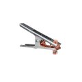
Hello everyone, I have a really nice HTP brand mig welder which is a igbt inverter circuit design. Previously I had a transformer/ bridge rectifier welder that I used a cast brass/copper ground clamp which in the professional welders arena is superior to a stamped steel alligator with braided copper strap clamp. The welder came with this stamp steel clamp and I replaced it with the cast copper/brass clamp thinking that the welder will function better(better arc quality). I was wondering that the path for the ground clamp would have a different resistance because of the larger mass of the cast vs stamped clamp. I recall resistance is proportional to the cross sectional area of the conductor. Anyway would I have any risks to damaging my welder which I hope never breaks as it’s a delicate and complicated inverter circuit vs a much simpler heavy transformer/rectifier type welder. I’m really rusty with my electronics from my school days, I’m just trying to visualize what could happen. Also, I see people using this same welder with the stock clamp included with the unit and it appears to be working well to the masses.
Did I get fooled into believing this gimmick if you will. These types of upgraded clamps could be made out of cheap pot metal and brass/copper coated. I have have attached some pics and would greatly appreciate some suggestions.

Did I get fooled into believing this gimmick if you will. These types of upgraded clamps could be made out of cheap pot metal and brass/copper coated. I have have attached some pics and would greatly appreciate some suggestions.
Attachments
-
 42.4 KB Views: 5


