 Facebook
 Google
 GitHub
 Linkedin
Hey guys,
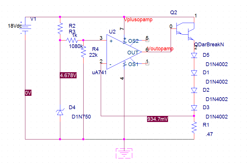
I am working on a variable 0-2A current source. The current source needs to be free from any spikes (because I have burned out too many laser diodes already). Here is the schematic I am using. The 1080KOhm resistor is actually a 80Kohm with a 1Meg potentiometer. When I power on the circuit the potentiometer is turned all the way up, so that the voltage at the noninverting input is very low. When the potentiometer is all the way down, it applies 1V at the noninverting input.
The bias voltages and currents on this schematic isn't updated with the present resistor values. (They are for when 1080kohm is changed to 80kohm)
Here is what I have measured so far:
The voltage at the zener diode is 4.8V. As I turn the potentiometer the voltage at the noninverting input DOES change just as it should.
However, the biggest problem is that while I (very briefly) plug the circuit in to test the current, it is reading 9.3 AMPS. The potentiometer doesn't seem to be doing anything either, as I read 9.3 amps with the pot all the way up and down. It is definitely changing the voltage at the noninverting input, though.
The darlington I am using is the TIP-120.
I have also measured the resistance from the inverting input of the opamp to ground, and it is between .4 and .5 ohms.
I am very confused because I thought the feedback would cause the particular transistor and op-amp parameters to be less important, but something is clearly wrong.
Sorry for the long post, I am hoping to give as much info as possible.
Thanks so much,
John
Last edited:


