Engine Start/Stop Button needs Help!!!

Thread Starter

Khaleef

Joined Mar 22, 2017
120
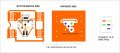
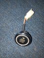
Please help with this Generator START/STOP Push button. It wouldn't start the engine but when engine is started by hand, the button would stop it.

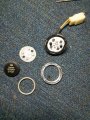
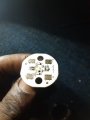
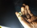
I have opened the button apart and found 3 tiny resistors with "101" on each. Please how do I check which is working and which is not. Looking at the button, the solution should not be too hard.

My gen engineer tried connecting a keystart with the same connect clip and the key starts the gen.
 

Attachments

Dodgydave

Joined Jun 22, 2012
11,395
I think the resistors are for the leds D1,3 for current limiting , they should read 100 ohms on a Dvm. Looks like there are 4 wires on the pcb, and four push contacts, i would say two wires for the leds, and two wires for the push switch .
 

Thread Starter

Khaleef

Joined Mar 22, 2017
120
I think the resistors are for the leds D1,3 for current limiting , they should read 100 ohms on a Dvm. Looks like there are 4 wires on the pcb, and four push contacts, i would say two wires for the leds, and two wires for the push switch .
Thank you Dodgydave, the PCB has 5 wires. Black,Green,Red,Yellow,Blue. How do I test the wires/button pads to know which signals the Engine to start. I am actually thinking of taking apart the keystart that worked starting the gen, can I use that reading to get the PCB?

Thanks.
 

Dodgydave

Joined Jun 22, 2012
11,395
You need an Ohm Meter or Multimeter on Diode test, and buzz out the wires to the connector from pcb, chances are that if there are 5 wires, then 2 will be the leds, 3 will be for the contacts.

There may be 1 common connection to the contacts and 2 switches.
 

Norfindel

Joined Mar 6, 2008
326
If you can see where every one of the cables are soldered in the board, that could tell a lot about their functions, but it seems like the tracks are on the other side of the board. Is the button capable of been lit in different colors?
 

Thread Starter

Khaleef

Joined Mar 22, 2017
120
If you can see where every one of the cables are soldered in the board, that could tell a lot about their functions, but it seems like the tracks are on the other side of the board. Is the button capable of been lit in different colors?
Thanks. Yes I can trace the tracks if I put the PCB over a brigth light. I would try draw out the diagram and upload soon.
 

dendad

Joined Feb 20, 2016
4,634
Often on those sorts of push buttons, they get dirty. Try cleaning the grid patterned pads (S1 to S4) and the black (usually) blocks on the underside of the white rubbery bit with alcohol. Some times I've drawn on the black bits with a pencil to make them a bit more conductive.
Don't use abrasive cleaning, just make sure there is no oily or dusty film on them.
 
Last edited:

Thread Starter

Khaleef

Joined Mar 22, 2017
120
Good day everyone. I really appreciate your contribution on this issue. So here I looked very clearly at the PCB and got the diagram.

The Button side is where we have the LEDS, Resistors and other Connects. The RED, BLACK, YELLOW, GREEN and BLUE point is where the soldered wires (with same colors) are soldered on the flip side pins out and connected to it's corresponding parts.

The ORANGE COLORS is used to denote the gold paths where connect passes. The WHITE DOTS on the orange are the tiny NEEDLE SIZES HOLES PERFORATED ON PCB which I understand to be point where connection takes to the other side of the PCB. The LED are leds and I0I is the resistors I think with the printed R1, D1... etc. The GREY color on the button side is to show that the connection happens on the flip side of the PCB. The interlocked Part is the SWITCH, like it is on calculators.

On the OPPOSITE SIDE, just a large big whole connection, and where the wires/cables are visible and where they are soldered. Also the perforated holes where it connects to the other side.

I have gotten a Digital Multimeter to check all connection (Beeps when connection is through) and they all connect EXCEPT the GREY LINE that connects the D3 and D2 LEDS, it didn't beep which I think it is supposed to.

Could that be a problem?

What else should I check/read/find out.

Thanks.
 

Attachments

LesJones

Joined Jan 8, 2017
4,511
I think the switch (Actually 4 switches in parallel.) uses conductive rubber on the underside of the white round thing below the 4 screws in the second picture. If I am right this item will be made of some kind of silicone rubber. Threre will be 4 black patches on the underside that are conductive. These should short the four groups of switch fingers on the board when the button is pressed. (This is the same princple a TV remote controls.) I suspect that this conductive coating is worn and not making good enough contact. Try connecting the button assembly without the button and rubber part. then try shorting the fingers on any of the 4 groups of fingers with a small screwdriver. If the generator starts then my theory is probably correct. It is possible to buy conductive paint to repair TV remotes.
The red wire should show continuity to the top connection on both LEDs 2 & 3 (That are shown linked by the grey track in your picture.) I Think a faut on that connection would only prevent these two LEDs from working.

Edit. I have just read your post #11 I think the switch might be working for stopping the generator but not starting due to the electronics requiring a lower resistance contact for starting than it does for stopping.

Les.
 

Thread Starter

Khaleef

Joined Mar 22, 2017
120
I think the switch (Actually 4 switches in parallel.) uses conductive rubber on the underside of the white round thing below the 4 screws in the second picture. If I am right this item will be made of some kind of silicone rubber. Threre will be 4 black patches on the underside that are conductive. These should short the four groups of switch fingers on the board when the button is pressed. (This is the same princple a TV remote controls.) I suspect that this conductive coating is worn and not making good enough contact. Try connecting the button assembly without the button and rubber part. then try shorting the fingers on any of the 4 groups of fingers with a small screwdriver. If the generator starts then my theory is probably correct. It is possible to buy conductive paint to repair TV remotes.
The red wire should show continuity to the top connection on both LEDs 2 & 3 (That are shown linked by the grey track in your picture.) I Think a faut on that connection would only prevent these two LEDs from working.

Edit. I have just read your post #11 I think the switch might be working for stopping the generator but not starting due to the electronics requiring a lower resistance contact for starting than it does for stopping.

Les.
About the conductive rubber, yes you are right. I have looked at it too when I opened the unit but I think it's still okay.

I would try shorting the contacts as you said and give reply.

I'm kinda lost at the electronic resistance part. Would that be on the generator part or the Switch/Button side? Because the engineer working on the gen used in Ignition Key Start on the clip and it worked
 

LesJones

Joined Jan 8, 2017
4,511
These conductive rubber contacts do not behave like metal contacts that would give a contact resistance of almost zero. I would not expect to get a reading of less than a few hundred ohms with conductive rubber contacts, You have proved that the fault is with this push button as you say it worked with a different type of switch.

Les.
 

Thread Starter

Khaleef

Joined Mar 22, 2017
120
These conductive rubber contacts do not behave like metal contacts that would give a contact resistance of almost zero. I would not expect to get a reading of less than a few hundred ohms with conductive rubber contacts, You have proved that the fault is with this push button as you say it worked with a different type of switch.

Les.
Yes you are right. I tried checking the contacts of the PCB to see if they are ok, I put the Multimeter on the "Continuity"(Beeper) (Lolz, apart from voltage, thats the next thing I can read in a meter)

So I placed the probes on the Blue and Yellow pin outs in the connector clip and pressed the rubber button and was expecting a beep but I was getting some readings instead. Now could it be the black substance on that rubber meant to activate the contacts are faulty ?
 

Thread Starter

Khaleef

Joined Mar 22, 2017
120
These conductive rubber contacts do not behave like metal contacts that would give a contact resistance of almost zero. I would not expect to get a reading of less than a few hundred ohms with conductive rubber contacts, You have proved that the fault is with this push button as you say it worked with a different type of switch.

Les.
So if the Push Button is the Fault and all the Paths on the PCB are through and not a part to say is faulty. Could it be the Conductive Rubber is the problem?
 

Norfindel

Joined Mar 6, 2008
326
That's strange. One would expect that any failure in the pushbutton would completely disable it for starting and stopping. Maybe the circuit at the generator side tolerates a higher resistance on the pads for stopping, but not for starting, or something like that.
You can probably try to activate the switch contacts with something else, like a piece of wire. To see if the generator starts, but probably the engineer should be the one doing that.
 
Top