Facebook
 Google
 GitHub
 Linkedin


The one's I've seen have a socket.I am seeing multimetres within Hfe range In no transistor socket.
Which ones are you seeing?
The one's I've seen have a socket.I am seeing multimetres within Hfe range In no transistor socket.
Me too.The one's I've seen have a socket.

Yep, that is my meter, the Transistor hFe tester is an accessory that comes with the box. I think you may have lost yours.i just looked through my DMM drawer and chose one that happens to not have a built in transistor test -AstroAI DM6000AR. i put it on resistance (even did not bother switching it to diode test, left it in autorange resistance) and decided to try use it exactly the same way as i did 1/2 century ago with analog meter... this is as quick and dirty as it gets.
the only differences are:
1. on my old analog meter black probe was positive when measuring resistance. on every DMM i ever had, red probe was always positive - even when measuring resistance.
2. values are going to be different since each meter uses different test voltage. this may not work if test voltage is too low so consider using highest range. best to try this on couple of parts you know what to expect before going after free range variety.
for this i grabbed random transistor which it turned to be 2N3904 (what a surprise ;-) ).
flat side up, pins towards me, left to right make mental note of pins 1,2,3. no resistance readings at all unless red is on 2 and black is on 1 (7.5M) or on 3 (6.8M).
one thing i make sure is that my finger only ever touch one DMM probe. so since base is on pin 2 and since positive probe was there to get some reading, this must be NPN type.
ok, so far so good, but everyone knows how to do this part. so what about C-E differentiation?
ok, i hold red probe on 1 using thumb and middle finger (this keeps index finger free for later). black probe is on 3 (no skin contact here!!!). resistance shown is infinite - until index finger is on base. the more i press the lower the resistance value. my skin is dry so by just using gentle touch i see value of some 40-45M. it can go lower than 20M but there is no point in enduring pain. ok.. value noted...
then i do the same but swap the sides.
so red probe is on 3, held by thumb and middle finger, black probe is on 1 (no skin contact here). resistance shows it is infinite. i touch base using middle finger again and try to use about same contact pressure as before. now i see 15M. this is the lower resistance value, so this is correct pin order. in other words, pin 3 is C (red probe), pin 1 is E (black probe).
for kicks i repeated this also on old MTP 2322 (without using its transistor test socket). this is ancient DMM with manual range selection so i set it on max resistance range (which uses higher test voltage). everything went EXACTLY as described but values were different, when determining polarity and finding base, i was reading 1.1M on both C and E when conducting. with wrong CE order, i was reading 8M, and in correct CE order it was 1M.
next tried Keithley 2000. forward biased junctions measured 55k/56k. gain test comparison showed values 7M and 1.1M.
EDIT: also just tried Fluke 83. same results... 30M/10M clearly says one is wrong and the other is correct.
have bunch more but further testing makes no sense.
the point is that different products even without built in BJT test, can be used consistently to determine pinout... power transistors have lower gain. do not pierce your skin, just wet your finger before test.
there are also pre-biased transistors where internal resistors are added. while principle is the same, this probably will not be practical (depends on gain and value of resistors)
so is this going to tell you gain of transistors accurately? NO! that depends on too many things that are not controlled.
can it be used to tell C and E appart? DEFINITELY! and it is FAST, does not need any other parts.

Hi,I just bought 4 meters from Amazon for $4.97 each (to give to my Science Olympiad kids), It's a model XL830L, but the meter doesn't have a brand name on it (makes you wonder how little someone wants to be associated with it). They just arrived yesterday afternoon and so far I've only had the change to do a couple of simple tests of resistance and DC voltage, but they match within a couple LSDs of my Fluke 77 and 27. The have two 4-pin connectors for transistor checking (EBCE), making it easy to check any pin configuration except if the emitter is in the middle (don't think I've ever encountered that). So I decided to go ahead and test that feature using the same transistors I tested the h_FE on earlier in the thread. As near as I can tell, there's actually no socket there at all. The transistor pins feel like they are just going through the plastic holes in the case into open space. I thought maybe it was just the first meter I pulled out, so I tried it on a second and it was the same. So I pulled one of them apart and it is exactly what I expected -- there is no socket there at all. However, the board does have the 2x4 holes for a socket and so I put the 2n3904 into the holes and tilted it so that I had connection and it gave a forward h_FE of 248 and a reverse h_FE of 3, which is quite consistent with my earlier measurement, particularly since it's almost certainly using a different current that I did. This made me suspect that it's a case of the model I happened to buy not coming with that feature, but going back to the Amazon listing indicates that it does, as does the instruction manual that came with the meter. Fortunately, if I can scrounge up suitable header sockets, I can "repair" these brand-new meters.
Hi,My free Centech multimeters from Harbor Freight has one of those, as do some of the <U$10 multimeters from Amazon.
I find that hard to believe. For one thing, the Beta can't be the same with the leads swapped.Several of my BC337 transistors have sufficient reverse gain to pass your test in both directions.
I didn't say the beta was the same, did I? The test doesn't require that the betas be the same, does it?I find that hard to believe. For one thing, the Beta can't be the same with the leads swapped.
Measure the CE voltage in both modes and see what you get.
No need. They appear to be good enough to completely satisfy the reason I bought them. In fact, I didn't even realize that they had a diode test mode, let alone a transistor test mode, when I ordered them. Since "fixing" them is easy, I might get around to doing it to one of them at some point, since none of my other meters have that capability. I left a review on Amazon so that others can be made aware of the issue and might consider it before purchasing if those are capabilities they are looking for.Hi,
You can get a refund for them if you are to take a few minutes typing or talking. If you go to Customer Service and talk to a representative and explain the problem they will refund if you ask for that, or give store credit, or perhaps offer replacements. They are very good with stuff like that and they often let you keep the merchandise too.
Hello again,I didn't say the beta was the same, did I? The test doesn't require that the betas be the same, does it?
And what do you base that negative opinion on?The spice models are probably not good for this which tells us something about how a lot of these spice models are made.
It's not a matter of better quality transistors have higher reverse gain. The reason for the lower reverse gain is the tradeoff to get higher collector-base and collector-emitter breakdown voltages. But different device topologies place this tradeoff at different points.Hello again,
If the gain is not the same, then probably all we need to do is change the collector resistor. I just threw one in there to show how the test works I did not go through any rigorous testing. The gain is somewhat known to be lower, but how much lower I don't know offhand.
I was asking so that maybe we could find out what would be required for that transistor part number. It could be that transistors with unusually high gain show more than the usual gain when the C & E leads are swapped, but it would take more thorough testing to find out. That's where you and your test jig come in
Now that I think about it, I am wondering if some of the Zetex transistors would show unusual behavior too in this backwards mode connection hookup. Some of them are very high quality with very, very low Vsat specs.
I've tested a lot of transistor like this in the past, but I am sure they were the more typical part numbers like probably 2N2222 and 2N4401.
The spice models are probably not good for this which tells us something about how a lot of these spice models are made. They are not made to act like the transistor, they are made to act like the transistor only when connected in a certain way, which assumes the circuit does not go into an unusual mode all by itself. That means they may not work in some real-life circuits because of the way the circuit works such as during startup. BR is supposed to model this though.
So the idea would be to get the test to work even with very high gain transistors if there is a problem there. If we see that the transistor acts too switch-like with the reversed leads (C and E but that is not known at the start of the test) then maybe we just need to lower the collector resistor and test again. Eventually we should see a big difference.
The BC337s seem to have not only significantly higher reverse gain (compared to transistors like the 2n3094, for instance), but it also seems to be pretty variable (though perhaps not as a percentage). I tested five of them (with ~60 µA of base current) and got beta values ranging from 36 to 114. Perhaps that spread would narrow if I use a higher base current.I also tested, and BC548B shows this result: β_F = 250 at 1mA and β_R = 8.3 in reverse active mode for the same current.
And for BC337-25 I'v got β_F = 352 ; β_R = 38
Hello there,And what do you base that negative opinion on?
It always amuses me that some that don't like simulators have never really used them.
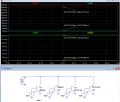
The LTspice 2N2222 model shows a forward beta of 143 and a reverse beta of 3, and the BC337-40 model shows a forward beta of 309, and a reverse beta of 33 at 1mA base current (below):
I believe those values are nicely within the ballpark for real devices.
What does that tell you about how "good" the models and how they are made?
What values did you measure with real transistors?
View attachment 372036
Yes it depends how symmetrical it is. But there is some relation that often exists even if not a hard and fast rule.It's not a matter of better quality transistors have higher reverse gain. The reason for the lower reverse gain is the tradeoff to get higher collector-base and collector-emitter breakdown voltages. But different device topologies place this tradeoff at different points.
| Thread starter | Similar threads | Forum | Replies | Date |
|---|---|---|---|---|

|
Is it OK to Step down from 800V to 24V with Emitter Follower like this? | Power Electronics | 28 | |
| V | Low Pass filter and Open Collector Input | Homework Help | 12 | |

|
Spreadsheet for Common Emitter Amplifier Design (BJT) - Look what I did! | Analog & Mixed-Signal Design | 14 |