Emitter follower example from Art of Electronics

Thread Starter

John544

Joined Dec 22, 2015
11
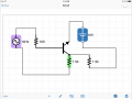
Hi- I'm struggling with the same example from AOE. I'm trying to enter the circuit into a simulator, but can't reproduce the expected result. Apparently I'm not imagining the undrawn part of the schematic correctly.

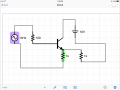
Would it be possible to get the entire schematic, so I can actually see this result?

Thank you, John
 

WBahn

Joined Mar 31, 2012
29,979
You've just practiced the art of necroposting -- this thread is nearly six years old and the thread starter probably hasn't been around for nearly as long.

However, you are at least not hijacking the thread (too much). It's probably best to let it stand this time.

A lot of people here don't have AoE, plus there is no indication of which version of AoE is being discussed and page numbers can vary from one printing to the next.

The best thing would be to copy the problem, including whatever circuit or circuit fragment they provide, so that we can all be on the same page.
 

Thread Starter

John544

Joined Dec 22, 2015
11
Thank you for your reply. I uploaded an image of the page. My question is about paragraph D. Thanks again. -John
image.jpeg

Mod edit: Reduced big, rotated image to thumbnail. Bertus has fixed it below.
 
Last edited by a moderator:

sjgallagher2

Joined Feb 6, 2013
131
I would check twice that you're using both a split supply: both +10V and -10V. Then make sure that you have the load resistor = emitter resistor, and that the load resistor is in the circuit at all! Finally double check that the load resistor is not in parallel with the emitter resistor, but is rather going from the emitter to ground. The emitter resistor goes to -10V. This is a tricky point, being made here. The 1k resistors have different voltages across them, and once the signal goes negative, ground will be above the emitter voltage. It takes a good comprehension of the voltages involved to really see why it will clip at 5V. When the emitter is positive, (i.e. the input signal is positive), it becomes the 'positive supply' for both of the resistors. But when it goes negative, only the emitter resistor, which is connected to -10v, will see it as a positive supply. Now that ground is above the emitter, current will flow from ground to wherever has the lowest voltage. That's the tricky part! Now where is this lowest voltage? Well if there's a voltage across a resistor, there's a current going through the resistor that is very easy to find.

While the emitter is above -5V, the emitter resistor will have a good current going through it, but that current will decrease as the voltage swings down through -5V. The load resistor, on the other hand, will have a current flowing that increases as the voltage swings from 0V to -5V and past towards -10V. Now we get to the point of this example: the resistors have the same value, and one increases as the other decreases in the voltage dropped across it and therefore the current going through it. Eventually they will cross over, i.e. they will carry the same current. Before this happens, by kirchhoff's current law, all the current from ground through the load resistor towards the emitter and emitter resistor will be carried by the emitter resistor. But once the load resistor carries more current than the emitter resistor, (think ohm's law here, the voltage is constant and the resistance is constant so for a given point on the curve it can only carry a set amount, whether it comes from the transistor or the load resistor), the only other place for the current to go is the emitter of the transistor. Which, you'll recall, is negative with respect to the load resistor and ground.

Thus, at the point where the load resistor carries more current than the emitter resistor, the transistor, which "can't sink current" and Horowitz and Hill say, will stop working. Current can't go into the emitter, which only happens when the emitter is lower than whatever is supplying it, and there's no other place for the current to go. This point happens, since both resistors have the same value, at halfway between the load resistors source (ground) and the emitter resistors negative source (-10V), aka it happens at -5V! Do the math, assuming a voltage on the emitter of 1V, -1V, -5V, and -7V for example, for the current through the emitter resistor and then the load resistor. You'll find that at -5V they carry the same current, and at -7V the load resistor carries more!

Hope you get the idea of what I'm saying. This idea is pretty complicated for a beginner to grasp quickly. Make sure you understand very well how current and voltage behave, try to avoid doing it mathematically but rather conceptually. Good luck!
Sam Gallagher
 

Thread Starter

John544

Joined Dec 22, 2015
11
Sam- Thanks so much for taking the time to provide a detailed reply. I'm going to go over it more carefully, but for right now I have a question about the split supply. I set this up in the simulator with a 10 volt AC supply at the input (base), and a 10 volt DC supply at the collector. Negative 10 volts goes to the emitter resistor, and the DC 0 volts goes to the load resistor.

I have a feeling that this isn't quite right. Also, I wasn't sure whether to use a series resistor with the AC power supply at the base.

Thanks again. -John
 

crutschow

Joined Mar 14, 2008
34,285
You have one power supply, not two as the example shows.
That is not an emitter follower circuit (the emitter is shown on the top of the transistor, it should be on the bottom).
 

Thread Starter

John544

Joined Dec 22, 2015
11
Sorry, please disregard that last schematic and use this one.

I'm trying to research how to make a split supply in a simulator but I'm still unsure how to do it.

Thanks again everyone for the help.
 

Attachments

blocco a spirale

Joined Jun 18, 2008
1,546
Sorry, please disregard that last schematic and use this one.

I'm trying to research how to make a split supply in a simulator but I'm still unsure how to do it.

Thanks again everyone for the help.
You might want to disregard this schematic as well since it won't work either. Details are important in electronics, as is drawing schematics as neatly and simply as possible without any unnecessary detours in the wiring. You just need to add another 10V supply to create the -10V rail.
 

Thread Starter

John544

Joined Dec 22, 2015
11
image.png Thanks Blocco. I agree about the wiring, but I'm working with this iPad simulator that insists on drawing the wiring strangely sometimes.

I've added a 2nd 10 volt supply, but am still not getting what I'm supposed to. Please see the attached.
 

crutschow

Joined Mar 14, 2008
34,285
Just copy the circuit shown in Figure 2.17 of your reference using two separate 10VDC supplies.
It has only one resistor, which is all you need for an emitter follower circuit.
 

Thread Starter

John544

Joined Dec 22, 2015
11
Thanks crutschow, but I'm not trying to make a simple emitter follower, I'm trying to recreate the circuit that clips as shown in the diagram.

Sam suggested that I use a split power supply, which I added, but apparently I still don't have it right.
 
Top