EMF Dropoff Protection

Thread Starter

arty4444

Joined Jun 9, 2017
21
image.jpg

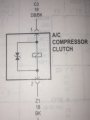
With 12V bat+ at top of shematic and ground to bottom my question is if the AC clutch coil shorts to ground causing a 40A auto reset circuit breaker to repeatedly trip will the Zener diode/ diode used for emf drop off protection fry or should it be OK (because it is not "seen" as a circuit path). While the current goes way up due to the short the voltage remains at about 12V because the coil never has time to magnetize?
Thanks in advance.
 

Attachments

bwilliams60

Joined Nov 18, 2012
1,450
It all depends on where the short is? I would assume since it is blowing a 40A circuit breaker, it is before the coil and not in the coil so therefore should take the path of least resistance. The coil will not energize and there will be no magnetic field. That diode you have there is a type of zener diode. It is a bi-directional TVS diode (Transient Voltage Suppression). It is unlikely it has suffered any damage but if you are replacing the coil, does it not come with the new one?
 

#12

Joined Nov 30, 2010
18,224
Lotta misconceptions. That zener looking thing does nothing for voltage drop protection. It just keeps the coil from back-sparking the wiring when the clutch turns off, and you get a new one with the new clutch, anyway. No matter where the short is, the magnetic field is going to be between crap and zero because a) the coil isn't getting any current or b) the coil is shorted.
You have nothing to worry about. This car circuit was built for people who don't know jack about electronics. I don't know how you can mess it up.
 

drc_567

Joined Dec 29, 2008
1,156
Check to see if the coil is shorted to the case:

... disconnect the power plug to the A/C coil. Next make a clean connection point on the A/C case someplace using emery cloth or something similar. Then test between each spade lug of the connector and the case. If you read 0, or just a few ohms, due to lead resistance, then the coil is shorted internally.
 

Thread Starter

arty4444

Joined Jun 9, 2017
21
I bought a clutch kit to repair the compressor and it did not come with a suppression diode nor was there one at or near the connector. The service manual says "find the diode in the wiring harness" which I can't even really access. Until I resolve diode issue by either replacing it or being fairly certain it is still OK I don't want to put the new coil in.
My original clutch doesn't engage. Disconnected the 2 wires at connector atop the compressor and on the 2 wires no longer attached to the clutch verified one is solid ground and the other supples power when A/C switched on.
On the other 2 wires still attached to the clutch but disconnected from connector I find the following; both leads indicate they are grounded (compressor still in vehicle), the tip of the power lead reads no resistance to the body of the grounded compressor and when jump wire from bat+ to coil power lead the jumper wire gets way to hot and blows a 60A fuse (in the jump wire) almost instantly. All this with both leads coming from out of the coil disconnected.
I admit I know little about electric circuits but thank you for your comments already posted as they give me the fair amount of confidence I need that my original diode is OK.
i have also started to look into putting my own diode (12V, 1A) at the coil connector but don't know if 2 working diodes could mess things up.
Thank you
 
I'm having a hard time following, period.

So, the funky diode is a TVS or basically a back to back zenier diode that's designed to handle surges. It basically makes polarity irrelevant to the coil.

Without it, the coil stores some voltage when it turns off and this can damage solid state drivers. The single diode approach, the anode is connected to (negative) and the cathode to positive. Just the reverse of a conducting diode. The diode should not conduct when the clutch is energized.

Two diodes are OK as long as they are in the right direction.

You have the clutch, so check for opens and shorts to the case. Some compressors only have one wire and the case is usually ground.

You can MAKE the clutch engage with jumpers to battery and ground. You might use a fuse, but the current is substantial.

Look at the power to the clutch separately in a "call for cooling" mode. Clutch disconnected. If you can't get anything meaningful, use a small real light bulb. e.g 194

My experiences: It took 17 years for a clutch to fail in one vehicle and that was from slipping. No other vehicles of mine or my parents, the clutches failed.

The usual failure is the lack of refrigerant and the low-pressure switch prevents the clutch from working.
I did put in a car AC system "from a box". It took about 14 hours. About every 7 years, the hoses would spring a leak. In the 17th year the clutch started to slip. It was time for a new car.

The "sold" car was "good enough" to be used in two robberies of VCR's and lawn mowers. I "gave" the car away to a dealership for $0.00. I should have at least sold it for $1.00 for the paper trail. I failed to notify motor vehicle that the car was sold. Lesson learned.
 

Thread Starter

arty4444

Joined Jun 9, 2017
21
My post previous to yours addresses most of your points although obviously in an unclear manner;

YOU ""You have the clutch, so check for opens and shorts to the case.""
ME- ""On the other 2 wires still attached to the clutch but disconnected from connector I find...the tip of the power lead reads no resistance to the body of the grounded compressor"" A short.

YOU ""You can MAKE the clutch engage with jumpers to battery and ground. You might use a fuse, but the current is substantial.""
ME ""...when jump wire from bat+ to coil power lead the jumper wire gets way to hot and blows a 60A fuse (in the jump wire) almost instantly. All this with both leads coming from out of the coil disconnected.""

YOU ""Look at the power to the clutch seperately...Clutch disconnected.""
ME ""...on the 2 wires no longer attached to the clutch verified one is solid ground and the other supples power when A/C switched on."" Additionally if all parameters including high and low refrigerant were not met there would be no power here from AC relay.

Your lack of serious AC problems is fortunate but Dodge Ram Vans are known for clutch coil failures. Your advice that redundant diodes are OK brings me to that as a fix as I no longer would have to be concerned about the condition of the original diode.

Thanks
 

bwilliams60

Joined Nov 18, 2012
1,450
I'm still a bit confused. The clutch coil just serves as the basis for an electromagnet so there are two ends to a coil of wire. One of them will get ground, the other power. If there are two terminals and you feed one ground and the other power, the compressor clutch should engage. This should occur with less than 30 amps and 14 gauge wire will suffice. If you are getting a hot wire and nothing happening, you have a dead short. Clutch coil is done. Replace.
The only other question not asked here is whether or not the compressor itself is seized. If it is, you are replacing the complete unit along with a receiver dryer and that is big $$$$$.
Good luck.
 

Thread Starter

arty4444

Joined Jun 9, 2017
21
I'm still a bit confused. The clutch coil just serves as the basis for an electromagnet so there are two ends to a coil of wire. One of them will get ground, the other power. If there are two terminals and you feed one ground and the other power, the compressor clutch should engage. This should occur with less than 30 amps and 14 gauge wire will suffice. If you are getting a hot wire and nothing happening, you have a dead short. Clutch coil is done. Replace.
The only other question not asked here is whether or not the compressor itself is seized. If it is, you are replacing the complete unit along with a receiver dryer and that is big $$$$$.
Good luck.
I DO know I have a short between the coil power lead (anode) and compressor housing probably out of sight between the coil and pulley.
My whole inquiry here concerns the shunt diode only which did not come with my new clutch kit and the original cannot be located in the wiring harness. Did the short fry the diode? From others here I gather its most likely OK but I can splice in a redundant diode just to be safe.
Armature turns by hand so compressor is not seized. Coil normally draws about 3.5A.
Thanks
 
If you get 12V at the connector, with the clutch coil disconnected, then there is no short to ground through a TVS or anywhere else for that matter.
Checking with an actual load, a bulb, is a good plan though.

The drawing you provided indicates that the TVS is part of the clutch unit, or possibly attached to its fixed wiring, you can tell this because it is shown inside the box along with the coil.

If you are sure the new clutch has no internal TVS then an external diode, or TVS is going to be required.
Personally I would use a diode but something big. If the coil is drawing 3.5A it is huge, in terms of a solenoid.

DC solenoids do not have an inrush current, in fact the inductance actually limmits the current rise, however many solenoid drivers limit holding current, by reducing voltage shortly after energising the coil, to reduce heating.
Some solenoids use contacts to turn off part of the winding or feed part of the winding through a capacitor which creates a current pulse.

It usually depends on the degree of change in geometry which dictates how much more current is required to pull the coil in in comparison to the current required to sustain the pulled in state.

At the very least assume the back EMF will produce a current at least equal to the initial current, and to be safe design for twice that because the solenoid is likely to open more quickly than it closed.

There is probably some complex maths you could do but then you would also need a raft of data or measurements you don't have and can't easily get, me, I just go OTT and dont worry about it, it not like it will cost much to have a huge margine of safety.

Al
 

Thread Starter

arty4444

Joined Jun 9, 2017
21
If you get 12V at the connector, with the clutch coil disconnected, then there is no short to ground through a TVS or anywhere else for that matter.
Checking with an actual load, a bulb, is a good plan though.

The drawing you provided indicates that the TVS is part of the clutch unit, or possibly attached to its fixed wiring, you can tell this because it is shown inside the box along with the coil.

If you are sure the new clutch has no internal TVS then an external diode, or TVS is going to be required.
Personally I would use a diode but something big. If the coil is drawing 3.5A it is huge, in terms of a solenoid.

DC solenoids do not have an inrush current, in fact the inductance actually limmits the current rise, however many solenoid drivers limit holding current, by reducing voltage shortly after energising the coil, to reduce heating.
Some solenoids use contacts to turn off part of the winding or feed part of the winding through a capacitor which creates a current pulse.

It usually depends on the degree of change in geometry which dictates how much more current is required to pull the coil in in comparison to the current required to sustain the pulled in state.

At the very least assume the back EMF will produce a current at least equal to the initial current, and to be safe design for twice that because the solenoid is likely to open more quickly than it closed.

There is probably some complex maths you could do but then you would also need a raft of data or measurements you don't have and can't easily get, me, I just go OTT and dont worry about it, it not like it will cost much to have a huge margine of safety.

Al
The short is pinned down somewhere in an inaccessable 6 inch long wire (coil anode). I get why you said I don't have a shorted diode from the connector back to the battery (because I'm getting power) but was concerned a diode in that circuit could have fried when the short elsewhere first happened leaving that diode in an open circuit by itself which would not open the remaining circuit to the coil.

I also thought the diode should have been part of the (OEM) clutch kit I bought because of the schematic but the only place it could have been was under the epoxy covering the coil windings which didn't seem likely.

Other sources not verified indicate the EMF collapse produces up to a 400V 1A back spike with more than one source reccomensing a "1N4004 clamping diode". Does such a diode sound reasonable to you or would you recommend another? I have been told that even if there is a functioning diode still in this circuit an additional one can't hurt- can you verify this?

I very much appreciate the time you (and others) have taken on this thread. I now know where (coil leads) and how (reversed) to place diode and finally need to pin down what diode.

Thanks

(Occultist Rudolf Stiener- "Electricty is condensed light")
 

Thread Starter

arty4444

Joined Jun 9, 2017
21
Thanks, I thought electronics would be an interesting field for casual study as a retiree. Casual won't really cut it- I'm starting about 45 years too late but still fascinated by the topic.
 

#12

Joined Nov 30, 2010
18,224
Thanks, I thought electronics would be an interesting field for casual study as a retiree. Casual won't really cut it- I'm starting about 45 years too late.
You're right...on both counts.
It's difficult enough to get a new technician fully competent on 12V DC circuits in the first year.
Throw in a half a dozen microprocessors and he doesn't have the chance of a fart in a hurricane.
 

Thread Starter

arty4444

Joined Jun 9, 2017
21
CHICKENED OUT;

With advice from this site and others I put together my spike suppression diode insert to splice between the coil wires on my new OEM replacement coil (orig. coil shorted). To recap I found no existing diode even though service manual indicated one and didn't know if it would still be good after short. I learned a second redundant diode would do no harm if correct polarities observed so ordered AC Delco PT 748.
i was using this part for its intended purpose but when checking resistance through the diode alone found zero resistance in either direction. In my first post the schematic calls for what I learned was a "bi-directional TVS Zener diode. Research indicated bi-directional did not really mean current suppression running in either polarity direction but rather suppression both above and below a threshold voltage range in one polar direction.
So with no resistance in either polar direction on diode I came to the uneducated opinion- this circuit is going to short through the diode as soon as the AC relay kicks in.
I did not splice it in.
Sitting in the auto shop now having the clutch kit installed I found the following- ""The alternative to a diode for protecting sensitive vehicle electrical components is to use a dedicated relay to switch the clutch on and off"". My schematic indicates such a relay. There are no other electronics (like PCM) wired between the relay and the AC clutch and no other devices or loads switched on/off by that relay. So I'm thinking when relay breaks circuit to disengage clutch a resulting reverse spike has nowhere to go to mess other components up. But where does that energy go- dissapates as heat in the coil maybe? That is what a diode causes anyway.
Anyway fingers crossed, Fl. hot, please just a clutch kit and NOT the whole $1500+ compressor route.
 
Comments:

Sometimes it's hard to know whether people mean infinite resistance for ZERO. Zero doesn't really exist sometimes. Zero R usually doesn't.
The TVS diode would be infinate, a high value or open in both directions when using resistance. Using the "diode mode" on your meter, it should read "OL" or Overload. In the "diode mode" the meter usually shows a voltage drop in volts, but not always true. I've heard some meters read in mV.

insert to splice between the coil wires on my new OEM replacement coil (orig. coil shorted)
Not between the coil wires, but across or in parallel with the coil.

The voltage across an inductor is given by the equation v= L* di/dt or a change in current induces a voltage multipled by the constant L or inductance. The change in current generates a voltage. So, the current in an inductor can't change instantaneously. This means the voltage has to go up.

TRUE, when the relay opens powering the clutch, the voltage has no where to go. The voltage MAY be large enough to poke though insulation and degrade it. it's not that likely. Formvar https://www.superioressex.com/uploa...merica/Magnet_Wire_-_Winding_Wire/Formvar.pdf (usual magnet wire insulation) won't break down < 9600 Volts. The 12 V automotive wiring MIGHT.

When the relay closes powering the clutch, There is also a change in current in the clutch current which also induces a voltage. In a modern car, the spikes are smaller. In older vehicles like pre 1960's the spikes in a car's electrical system are larger. Most of the come from the alternator. +50 to -200 V are common. http://www.littelfuse.com/~/media/e...n_automotive_environment_application_note.pdf

The activating relay has a coil of it's own. The single diode is usually used there to protect the solid state device driving the relay coil.

I'd need to hunt for variations in older and newer vehicles.

The time of the greatest damage would occur when the clutch is cycling and primarily on activation. That spike may be absorbed by he rest of the vehicle. You want to suppress the spike as close as possible to the source.

This likely is why the choice of a bidirectional TVS was made. Rapid cycling such as when the low pressure switch opens intermittently when the refrigerant charge is low.

Your analysis isn't bad. You need the v(t) = L di/dt; the current in an inductor can't change instantaneously; the notion of breakdown; and the repetiveness of the generating a large voltage on an airconditioning fault (low freon charge).

Furthermore, the modern car is designed with local transient suppression in mind and the alternator being probably the largest contributer is designed with suppression in mind too. AM radio ignition noise is virtually gone with a coil per 2 cylinders because the high voltage wires are really short.

Research indicated bi-directional did not really mean current suppression running in either polarity direction but rather suppression both above and below a threshold voltage range in one polar direction.
So with no resistance in either polar direction on diode I came to the uneducated opinion- this circuit is going to short through the diode as soon as the AC relay kicks in.
I'll modify your statement to:

bi-directional means voltage suppression in either polarity above and below a threshold voltage (e,g, > 20 V, <-20 V) So, with no measured resistance (i.e. Open) with my meter, in either polar direction on diode I came to the opinion- this circuit is going to short through the diode as soon as the AC relay kicks AND the thresholds above are met.

Since the current in an inductor can't change instantaneously, a voltage must be developed across the coil. The voltage can be developed when the coil is switched on or off. The greatest danger is when the compresser rapidly cycles under a fault condition.


So with no resistance in either polar direction on diode I came to the uneducated opinion- this circuit is going to short through the diode as soon as the AC relay kicks in
 

crutschow

Joined Mar 14, 2008
38,503
"No resistance" is not obtainable except for a superconductor which does indeed have zero resistance.
The resistance may be some value near zero, indicating a possible short, or the meter indicates an OL or or other indication of a resistance higher than the meter can measure, which is an open.
Please use the terms open or short (or the actual measured resistance) when reporting your resistance measurements.
 
Top