EM Induction demo

Thread Starter

Tutor88

Joined Feb 8, 2023
306
Hello again,

With term finished in effect, I told my student that over the holidays I would construct a model for them to show the basics of electromagnetic induction using magnets.

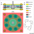
The basis for my model is shown in the diagram and consists of a wooden disc with four magnets stuck to it with N (or S) poles facing out. The disc can be hand cranked or driven by a small motor.

The pickup I propose to be a series of wire loops on another wooden base (think ping pong bat) so I can move it in and out and where the coils are wired in parallel (only one set of wires is shown here). The output would then presumably need to be rectified and smoothed to give a DC current.

My queries are:

1. Is this the most effective method of extracting energy from the rotating magnets

2. Would one big coil be more effective than the four smaller ones (as shown)

3. How much capacitor smoothing might be required to give a usable DC current?

Thanks
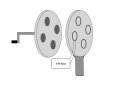
Induction model.jpg
 

LowQCab

Joined Nov 6, 2012
5,101
1) No, in fact it's quite inefficient.

2) No

3)
What do You consider to be "Usable-Current" ?
It's easy to generate enough Voltage to have it register on a Volt-Meter,
but don't expect to get very much "Power" ( Volts X Amps ) from this setup.

If You want to actually operate something like an LED, or a miniature Motor,
this can be accomplished with a few guidelines .........

Use 8 magnets instead of 4, there should be as little space between the Magnets as possible.
There must be an even number of Magnets.
More Magnets is better.
Larger diameter Wheels are better.
The Pole-Polarity of the Magnets must alternate, ( N,S,N,S,N,S,N,S ).
The Magnets need to be the biggest, strongest, Neodymium-Magnets that You can fit on to your device.
The Coils need to have as much wire in them as is practical, this means using very thin Wire, ( maybe ~24ga. ).
There needs to be a Coil for every Magnet, and they must have reasonably close alignment to the Magnets.
The distance between the Coils and the Magnets must be as small as is practical.
The Wiring of the Coils must be done in such a manner as to insure permanent, and easy polarity identification.
The Coils should all be wired in Series, paying close attention to their Polarity ( + - + - + - + - + - ).

If You need DC-Power instead of AC-Power,
a generic Bridge-Rectifier rated around ~5-Amps and ~400-Volts should do fine.
The Voltage-Output of this Alternator is NOT REGULATED,
and could possibly exceed 100-Peak-Volts with no Load attached, and a very fast spin.
The Bulk-Storage-Capacitor, ( if desired ), can be easily damaged by
excessively high-Voltage if the Generator is spun very fast with no Load attached to it.
The Capacitor should be rated at ~50-Volts or more to avoid an accidental Capacitor-Explosion.
A Capacitor is not necessarily required for a DC Output.

Following these guidelines should produce enough Power to
spin a very small 5-Volt Hobby-Motor with a small Propeller attached, or possibly ~10 to ~20 LEDs.

If using LEDs,
a proper active Current-Limiting-Circuit will have to be employed to keep from routinely destroying LEDs.
.
.
.
 

Ya’akov

Joined Jan 27, 2019
10,231
You might consider building a model of Faraday's Disk (possibly in addition), you will be best served with a moving needle millivolt meter, like this one (-20mV to 20mV), to show the induced power which will be quite small.

It was one the demos that Faraday built for the Royal Academy. Faraday was an autodidact who was exceptionally good at building experiments. Lacking a college education, he didn't use math in his work and building physical embodiments of the ideas allowed him to understand things more clearly.

His first induction demo, to demonstrate his discovery to the academy was a simple toroidal transformer with a switched power source connected to one winding, and a meter to the other. When the switch was operated, the meter jumped. This was induction from the first coil as the voltage rose, into the second.

He didn't have the idea of a transformer when he built it, but eventually the same idea was applied to AC for many purposes.

You will find many sources for educational materials concerning Faraday's Disk.

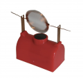
There is a very nice demo (a kit version of which I designed for a third year EE E-Mag class) that is a very simple motor using a battery and a coil of wire. Permanent magnet motors are dynamos in reverse, so it's the same idea—instead of suppling motion and getting current, you supply current and get motion.

There are many versions of this motor, but a common pattern is this one:

1686825241913.png
Only an example, available here.
Inside the base is a D cell, the black circle is a magnet. My kit used an open battery holder to make is more clear and a ceramic bar magnet that easily stuck to the cell eliminating any extra mounting.

When I built science museum exhibits I focused on simplicity to take things to their essentials and let the visitor see the fundamental bits needed. While you might want to have something more complex than these two, I think there is a great pedagogical value is at least starting with stripped down demos so the students have a chance to understand the principles.
 

Thread Starter

Tutor88

Joined Feb 8, 2023
306
Thank you for the suggestions and advice. I have to balance effectiveness with effort but perhaps building a 'good' version will be fun in itself and useful if it can generate a useful (10W?) amount of power.

Is there a way to estimate such power output if, say I drive the magnet wheel with a motor at 1000 rpm and I used small Neo 20mm by 3mm thick magnets (4.5kg pull)? Just a ball park figure.
 

MisterBill2

Joined Jan 23, 2018
27,445
Another scheme is to use a laminated iron core filter inductor, having a coil resistance of about 100 ohms.
It should be the E-I lamination type, with the "I" section temporarily removed. A small 6 volt pilot light is connected across the leads. The demo I saw used a fairly strong bar magnet first placed touching the core center and then quickly pulled away, producing a light flash. That was in a seventh grade science class back in 1960. Quite some time back. Different sizes and powers of magnets can produce different voltages.
 
Last edited:

wayneh

Joined Sep 9, 2010
18,100
10W is not possible from the arrangement in #1, even if you could get a very small gap between the rotor magnets and stator coils. I think you'd have trouble getting over 1W.

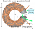
One major problem is that there is no complete magnetic circuit. Well, the field lines do make a "circuit", but through air. You need a hunk of iron to direct the field lines back to the other pole of the magnet. The arrangement in #3 accomplishes that. Here's another arrangement that does that:
1686846399649.png

The point is to drive the magnetic field lines through as many conductor loops as possible - that's what creates EMF.

It's then very important to match the load impedance to the coil impedance. Hundreds of turns of fine wire will give you more voltage but less current. Fewer turns of heavier wire can support more current but you'll get less voltage.
 

Thread Starter

Tutor88

Joined Feb 8, 2023
306
When I have completed my version using a series of Neo magnets on a disc, what would be an ideal full wave rectifier chip to use? They can be quite chunk and I’m trying to keep it small.

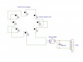
I’m thinking first of the DB107 bridge rectifier and with a 1000uF, 50V smoothing capacitor across the DC output. Would that be ok?
 

MisterBill2

Joined Jan 23, 2018
27,445
Another scheme is to use a laminated iron core filter inductor, having a coil resistance of about 100 ohms.
It should be the E-I lamination type, with the "I" section temporarily removed. A small 6 volt pilot light is connected across the leads. The demo I saw used a fairly strong bar magnet first placed touching the core center and then quickly pulled away, producing a light flash. That was in a seventh grade science class back in 1960. Quite some time back. Different sizes and powers of magnets can produce different voltages.
Really, this same scheme can be used with a pendulum suspending a stronger magnet so that it passes the three legs of the "E" core in sequence. this can provide three pulses that could flash a 2-lead bi-color LED both colors. The magnet will need to be oriented so that it's flux points down toward the laminations.
This arrangement would be very good for hands-on demonstrations.
 

WBahn

Joined Mar 31, 2012
32,796
A lot depends on what you REALLY want to accomplish with the demo. Is it to convince them that electromagnetic induction is real? As in, they might not be truly convinced otherwise? Is it to power some specific thing? Or is it just to get them engaged in the learning and exploration process?

If it's the latter, then things like power and efficiency don't matter. You just want something cool that demonstrably works.

Also if that's the case, I would try to not just have them watch a demo, but have them get their hands dirty building something real simple that works.

There are lots of demo kits you can buy that are cheap and interesting, but I've always found that a really engaging demo is you give them a C-cell battery, a battery holder (or duct tape, but the battery hold makes it a lot easier), two paper clips, a neodymium magnet, a length of enameled wire, and a small piece of sandpaper.

Then you show them how to make what you refer to as "the world's simplest motor" by rapping the wire around the battery a bunch of times, leaving an inch or so of wire on each end. You slide it off the battery and wrap the ends around the windings to hold them in place and leave them sticking straight out. You then sand the enamel off one side of each of the ends. Now you bend the paper clips so that when you lodge them between the two ends of the battery and the holder they stick up making a small cradle high enough up so that you can rest the coil across them. You then put the magnet on top of the battery (i.e., on the side of the battery as it sits in the holder) and position the coil so that as it turns it barely misses the magnet. If you now give the coil a gentle rotation it will start turning on its own. If the coil is well balanced, it will turn surprisingly fast.

Even adults love this and it's engaging because there's no "kit magic" involved -- it's unassuming pieces parts that they have taken and formed with their own hands into something that is more than the sum of its parts.

Once they have done this, you can give them an AA battery, a magnet, and a short piece of bare copper wire (solid) and have them make an even simpler magnet by shaping the wire into a heart shape, putting the magnet on the negative terminal of the battery and placing the wire so that the center dimple of the heart is on the positive terminal and the ends are bent so that they scrape the side of the magnet. This creates a homopolar magnet.

You can do other projects that have them generate enough electricity to light an LED, and as long as they are taking parts the seem routine everyday items and crafting some kind of generator, it doesn't matter how inefficient it is or how little useable power it can produce.
 

Ya’akov

Joined Jan 27, 2019
10,231
There are lots of demo kits you can buy that are cheap and interesting, but I've always found that a really engaging demo is you give them a C-cell battery, a battery holder (or duct tape, but the battery hold makes it a lot easier), two paper clips, a neodymium magnet, a length of enameled wire, and a small piece of sandpaper.
I mentioned this above, but it is my impression that the TS wants something more “dramatic”. I, too, believe it is less interactive to have a complicated device, and more difficult to explain how it relates to the theory, but the TS is the instructor and should know his students’ propensities.
 

WBahn

Joined Mar 31, 2012
32,796
I mentioned this above, but it is my impression that the TS wants something more “dramatic”. I, too, believe it is less interactive to have a complicated device, and more difficult to explain how it relates to the theory, but the TS is the instructor and should know his students’ propensities.
Apologies. I was just trying to offer a perspective for consideration. Please disregard.
 

Thread Starter

Tutor88

Joined Feb 8, 2023
306
The points are valid, but given that I only want to build one device in the future, for use with other students, then I would like to be able to extract the most power/voltage from it and show the rectification and smoothing process. I teach A-level students too who need a more complete and complex understanding. Then I can deconstruct the mechanism graphically down to the appropriate level as required. There is always going to be a student in the future who will say ' Why couldn't you get it to do . . . . . . :rolleyes: "

Any thoughts on the suggested DB107 rectifier chip and 1000uF cap?

Thanks
 

Ya’akov

Joined Jan 27, 2019
10,231
The points are valid, but given that I only want to build one device in the future, for use with other students, then I would like to be able to extract the most power/voltage from it and show the rectification and smoothing process. I teach A-level students too who need a more complete and complex understanding. Then I can deconstruct the mechanism graphically down to the appropriate level as required. There is always going to be a student in the future who will say ' Why couldn't you get it to do . . . . . . :rolleyes: "

Any thoughts on the suggested DB107 rectifier chip and 1000uF cap?

Thanks
I would use four 1N4007 diodes so the bridge configuration is plainly obvious, and for the capacitance, I would use two or three smaller values in parallel if space is a problem, say 330μF at the appropriate voltage.
 

MisterBill2

Joined Jan 23, 2018
27,445
Consider that diodes have a forward voltage drop that must be exceeded before they conduct very much. It is quite possible that some generation schemes will not deliver that much voltage. And no matter what voltage is delivered, there will be a threshold effect that will tend to hide the relationship between the rate of change and the voltage produced.
Just waving a magnet past a coil wrapped around a steel core, such as a few nails, or a larger diameter steel bolt, can produce a very much hands-on experience of generating a pulse, while also delivering the feel of magnetic attraction. In addition, it would be simple
 
Last edited:
Top