Facebook
 Google
 GitHub
 Linkedin
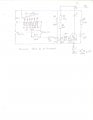
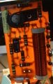
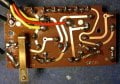
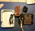
Can someone perhaps help to identify a transistor?? in the control circuit. I have a circuit worked out, correctly I hope, but the single transistor on the board which controls the current to the motor has NO MARKINGS!! The part is perfectly functional but one capacitor on the board had failed causing the motor to run continually without the foot control depressed. Got everything back to normal but would like to go further with the design.
Would upload a schematic but can't see how to do it.
Would upload a schematic but can't see how to do it.