Facebook
 Google
 GitHub
 Linkedin
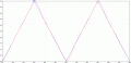
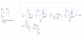
I add another integrator circuit which makes the circuit a 2nd order circuit with a gain of 2 before the Vin enters the summing amplifier. Through simulation the error is reduced to 160mV but practically dosent workHello again,
I took another look at this and it looks like what you are talking about might better be described as an offset. To eliminate offset you have to use either an adder or subtractor.
If you have say 0.3v offset then you subtract 0.3v offset.
If the offset is related to the input then you have to use a special circuit to calculate the offset and apply that to some place in the circuit.
But what methods have you been taught so far? That would help determine what way they want you to do it.
Eliminating Steady State Error
- Thread starter richard_lai
- Start date