Facebook
 Google
 GitHub
 Linkedin
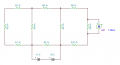
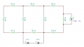
Ohm's law says that R=V/I so for resistor 1, 1Volt divided by .oo14 amps equals 714, so in the circuit for resistor1 = 714 Ohms even if it is a 1K ohm resistor. R1,2,3 are in a series whereas R4 is a parallel of R7. Again this is the readings I took with a multimeter and they are accurate enough. I need to figure out how to solve this circuit with Ohm and Kirchoff's laws without making a single multimeter reading.The OP opened his statement with "ALL RESISTORS ARE 1k."
The OP's diagram does not reflect that tidbit of information.
Does the OP know ohms law? 1 volt across a 1kΩ resistor does not equal 1.4 mA. Did the OP measure the current? I doubt it.
Granted, there is a tolerance in real life. Did the OP measure the resistances before constructing the circuit? The information is scare.
I'm sure the OP's lab assignment had specific criteria. He did not share anything other than his diagram.
Electronics 101 HELP
- Thread starter Sberndt6853
- Start date