I'm tempted to say "you're getting warm" --- But again, please know that you are already possessed of the requisite skills! -- That said, I'm pleased to see you making an effort to research the subject!
Note:
Compensation aside -- An 'L' matching network is composed of two reactances being of opposite sign...
Don't be confused should you encounter 'L' matching networks comprised of reactors bering like signs -- Such 'arrangements' occur when subsumption of a port reactance (i.e. compensation) requires a 'sign reversal' of a network reactance -- the effective reactances will be of opposite sign...
NOTE: 'L' (in this post) refers to the network geometry -- not to inductance!
While Kirchhoff's laws form a useful frame of reference -- apprehension of the problem at hand (i.e. post #113) requires your attention to the implications of positive and negative reactance/impedance (as illustrated in post #145) -- That said: Generalization of Kirchhoff's laws (and of fundamental electrical relations) so as to 'embrace' said implications may be very useful indeed!
Now I'm giving _knock out punch_ by saying
Q is proportion of reactance to resistance so like Qp=R/X and Qs=X/R. Now I am saying answer is the 800 lbs gorilla riding elephant through room!
I am same generation as you so is appropriate for me to say get with it dude!
Now that @Aleph(0) has taken it upon herself to leave nothing to imagination --- I expect 'results'...K?
As an aside: Note that 'Q' is, as a practical matter, independent of transformation ratio in networks comprised of three or more distinct reactors -- as you will see should you choose to continue this line of study!
It occurs to me that the 'block' you seem to be experiencing with the current exercise may owe to misapprehension as regards impedance transformation via networks (arrangements) of discrete reactors...
Here I present an example of transformation of 10v to over 60V via a series resonant RLC circuit --- While not directly applicable to the exercise, this is intended to set you upon the right path! Note that, with some qualification, impedance may be thought of as EMF to current ratio!
Please note that following is not to be confused with other impedance transformation schemes/phenomena (i.e. mutual inductance, 'buck/boost', etc...)
I hope you find this helpful!!!
/////////////////////////////
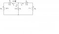
Within the confines of this discussion, resonance is a condition wherein 'opposite' reactor types exhibit reactances of equal magnitude but opposite sign and, hence, 'cancel' -- Below is a representation of a series RLC circuit at resonance -- Please consider the following:
Because EMF lags current by 90° in a purely reactive, net capacitive circuit, capacitive reactance is said to be negative.
Because EMF leads current by 90° in a purely reactive, net inductive circuit, inductive reactance is said to be positive.
With reference to the below attached schematic:
Reactor 1 (The capacitor) exhibits a reactance of -2πΩ @ a frequency of 100MHz
Reactor 2 (The inductor) exhibits a reactance of 2πΩ @ a frequency of 100MHz Hence the circuit is said to be resonant @ 100MHz
Owing to their series connection, the net reactance = the sum of the reactances = 0Ω. Thus the net impedance = the value of R = 1Ω
Thus it is that the current through the circuit is determined by the EMF of the power supply (1oV Peak) and the resistance of R (1Ω) →10V (Peak)/1Ω= 10A (Peak)
Ohm's law tells us that the EMF across a pure reactance = I*X = 10A*2π ≈ 62.83V in the case of the inductor --- And 10A*2π ≈ -62.83V in the case of the capacitor (note that the signs indicate the respective phase shifts)
In theory any finite transformation ratio is possible via proper choice of the reactors and the resistor.
Illustration of a series RLC circuit at resonance -- Post continued below image... View attachment 97569
As an aside please consider a parallel resonant circuit.
Via the technique of calculating the equivalent value of paralleled resistors or pure reactances:
1/(1/Xc+1/Xl)=Xnet but since Xc=-Xl at resonance: 1/(1/-x + 1/x) = 1/(0/x^2)=1/0 = ∞ (For these purposes) Thus we see that a parallel LC circuit at resonance presents as an 'open circuit'
example of transformation of 10v to over 60V via a series resonant RLC circuit --- While not directly applicable to the exercise, this is intended to set you upon the right path!
There is 10V sinwave source of 10A??
by applying the AC voltage to inuctor it give back EMF which is absorb by Capacitor?
I say HP was giving the _velvet glove_ when she said
Now I'm giving _knock out punch_ by saying
Q is proportion of reactance to resistance so like Qp=R/X and Qs=X/R. Now I am saying answer is the 800 lbs gorilla riding elephant through room!
I am same generation as you so is appropriate for me to say get with it dude!
example of transformation of 10v to over 60V via a series resonant RLC circuit --- While not directly applicable to the exercise, this is intended to set you upon the right path!
There is 10V sinwave source of 10A??
by applying the AC voltage to inuctor it give back EMF which is absorb by Capacitor?
Each reactor exhibits a reactance having a magnitude exactly = 2πΩ
So the inductor exhibits a reactance of 2πΩ
The capacitor exhibits a reactance of -2πΩ
Pure reactors compound in a manner similar to resistors -- thus the net reactance: 2πΩ in series with -2πΩ = oΩ
Hence, within the confines of our ideal model, the 1Ω series resistor is the sole current limiting 'element' --- Thus, via Ohm's law: 10V/1Ω = 10 Amperes
Thus the 'voltage' across each reactor (Again, via application of Ohm's Law):
10A*2πΩ=20πV≈62.83V (Across the inductor)
10A*-2πΩ=-20πV≈-62.83V (Across the capacitor)
Note that the sign on the EMFs indicate the 'chirality' of the corresponding phase shifts...
 Facebook
 Google
 GitHub
 Linkedin

") --- But again, please know that you are already possessed of the requisite skills! -- That said, I'm pleased to see you making an effort to research the subject!
--- But again, please know that you are already possessed of the requisite skills! -- That said, I'm pleased to see you making an effort to research the subject!