Electric motor wiring help needed

Thread Starter

4ePikanini

Joined Feb 6, 2012
11
Hi

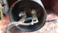
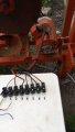
I am busy refurbing a bench saw. It came with a motor which I suspect is an old washing machine motor. It has seven wires coming out of it and an old cap with a resistor. I just need it to run one speed to power the table saw. It came with a single three point plug so I (hopefully not wrongly) assume it is a single phase 240V AC motor. Where would I connect live and neutral (and perhaps jumper some terminals)?

I removed the cap and resistor and did some measurements

NB : The wiring itself is printed and numbered 2 to 7 as per my pictures.

capacitor spade female connection 1 has continuity to 5 (ie. resistance of about 0.1 ohm)
capacitor spade female connection 2 measured to......
- 3 :11 ohms
- 4 : 8.5 ohms
- 5 : 8.5 ohms

Terminal 2 measured to......
- 3 : 3.2 ohms
- 4 : 3.2 ohms
- 5,6,7 : open

Terminal 3 measured to.......
- 4 : 0.5 ohms
- 5,6,7 : open

Terminal 4 measured to.......
- 5,6,7 : open

Terminal 5 measured to.......
- 6,7 : open

Terminal 6 measured to......
- 7 : 0.5 ohm

Many thanks in advance.
Marius
 

Attachments

Thread Starter

4ePikanini

Joined Feb 6, 2012
11
Normally that info would be inside the terminal cover.
What is the manuf of the motor?
Max.
The placard has been painted over, and my efforts to get to the info underneath has failed.

In addition.

If I have live on terminal 2, and get the motor spinning by hand I can put neutral on 5 and it will keep spinning slowly. If I then quickly remove the neutral wire from terminal 5 and join it (while motor is still turning, but slowing down) to terminal 4 (or 3) the motor turns perfectly at speed.

So it's just the startup thats an issue.

Brand new capacotor is also installed with bleed resistor and it makes no difference.
 

MaxHeadRoom

Joined Jul 18, 2013
28,617
Going by the size of the capacitor it appears to be a start capacitor, i.e. switched out when up to run.
If so there is normally a centrifugal switch or an external current relay to switch it out.
Max.
 

LesJones

Joined Jan 8, 2017
4,174
I think there is an error in your table of resistance readings.
You say that the resistance from capacitor terminal 2 to terminal 4 is 8.5 ohms
You say that the resistance from capacitor terminal 2 to terminal 5 is 8.5 ohms
So the maximum resistance between terminal 4 and terminal 5 must be 17 ohms
BUT later you say terminal 4 to terminal 5 is open so there must be an error in one of these statements.

You get readings of 0.5 ohms between terminal 3 and 4 and also between terminals 6 and 7. I will assume this is wiring or test lead resistance so I suspect the centrifugal switch is connected between terminals 3 and 4 or terminals 6 and 7
Can you spin the motor up about it rated operating speed using an electric drill or other means and test if the connection between 3 & 4 or 5 & 6 open. (Showing that those are connected to the centrifugal switch.) Also do you know if the motor is dual voltage (120 / 240) ? That is only likely if it is of American origin.

Les.
 

Thread Starter

4ePikanini

Joined Feb 6, 2012
11
It definitely has a centrifugal switch. It moved freely when I had the back of the motor open.

There is also a small component inside the motor attached to the rear casing (inside). I believe it had a wire labeled 1 that came from the motor, passed through this component and then exit to terminal three.

There was continuity between terminal 3 and wire 1.

I will double check my ohm readings Tuesday when Im back at work.

Any additional measurements or test that I need to do?

Many thanks for the help so far.
 

LesJones

Joined Jan 8, 2017
4,174
As you are familiar with taking the motor apart it may be easier to do that and trace the wires to the centrifugal switch. You could also take a photograph of the unknown component inside the motor and one of us may be able to identify it.

Les.
 

Thread Starter

4ePikanini

Joined Feb 6, 2012
11
As you are familiar with taking the motor apart it may be easier to do that and trace the wires to the centrifugal switch. You could also take a photograph of the unknown component inside the motor and one of us may be able to identify it.

Les.
Im quite capable and happy to take the motor apart.

Will do so Tuesday if it will make it easier for someone more knowledgable than me to help wire it up.

Thanks.
 

LesJones

Joined Jan 8, 2017
4,174
I have come up with a theory that could explain the behaviour in post #3. This is how I think it is connected. Capacitor terminal 2 is connected internally to one end of the start winding. The centrifugal switch is between terminal strip connections 3 & 4.. The other end of the start winding is connected to either 3 or 4 (We don't know which as the centrifugal switch is closed.) but for now we will say it is 4. One end of the run winding is connected to 2. The other end of the run winding is connected to 3 or 4. We will say 3 for the moment. With the initial connection of live to 2 and neutral to 5 starting from 5 the start capacitor, the start winding , the centrifugal switch and the run winding are connected in series in that sequence finishing at 2 (Live.)
When neutral was connected 3 or 4 the run winding would be straight across the mains so the motor would run up to speed. If it was connected to the side of the centrifugal switch that was connected to the run winding the motor would continue to run. BUT if it was connected to the other side of the centrifugal swicht I would expect the motor to cycle up and down in speed as the centrifugal switch opened and closed. The fact that the motor continued to run with neutral connected to either 3 or 4 suggests the centrifugal switch is not opening. OR 3 and 4 are the thermal switch and the centrifugal switch connects to 6 & 7 I think 2 and 5 should be linked and connected to live and live connected to the side of the centrifugal switch that is connected to the run winding. Before doing this it needs to be confirmed that the centrifugal switch is connected between 3 & 4 and that it does open when the motor is up to speed.

Les.
 

Thread Starter

4ePikanini

Joined Feb 6, 2012
11
Hi

I have some extra info for you.

5 Goes to one terminal of the capacitor
The other terminal of the capacitor goes to the motor
Terminal 4 goes to the motor
Terminal 2 goes to the motor

6 & 7 is on the centrifugal switch at the back of the motor

Thanks.
 

Attachments

LesJones

Joined Jan 8, 2017
4,174
It looks like my theory in post #10 is wrong. In the third picture you have a wire marked 1 on the bottom connection to the component that we think is a thermal cutout but in post #1 there is no wire connected to terminal 1 of the connector strip. Can you explain ? In post #6 you say "There was continuity between terminal 3 and wire 1." I only noticed this today and probably before I read it as terminal 1 (As opposed to wire 1) Where is wire 1 ?

Les.
 

Thread Starter

4ePikanini

Joined Feb 6, 2012
11
It looks like my theory in post #10 is wrong. In the third picture you have a wire marked 1 on the bottom connection to the component that we think is a thermal cutout but in post #1 there is no wire connected to terminal 1 of the connector strip. Can you explain ? In post #6 you say "There was continuity between terminal 3 and wire 1." I only noticed this today and probably before I read it as terminal 1 (As opposed to wire 1) Where is wire 1 ?

Les.
Wire one goes to the motor.

Ie. Wire one and three is the same, but is joi.ed together by that component which shows continuity over the contacts.
 

LesJones

Joined Jan 8, 2017
4,174
This is how I think the windings are connected in the motor.
150420.jpg

I don't understand why there are two wires brought out to terminals 3 & 4 that seem to go to the same point. If the wires had gone one to the end of the run winding and the other to the end of the start winding the motor could be reversed. I think terminal 5 should be linked to terminal 6. Live should be connected to wire 1. Neutral should be connected to terminal 2 and terminal 7.

Les.
 

Thread Starter

4ePikanini

Joined Feb 6, 2012
11
This is how I think the windings are connected in the motor.
View attachment 204351

I don't understand why there are two wires brought out to terminals 3 & 4 that seem to go to the same point. If the wires had gone one to the end of the run winding and the other to the end of the start winding the motor could be reversed. I think terminal 5 should be linked to terminal 6. Live should be connected to wire 1. Neutral should be connected to terminal 2 and terminal 7.

Les.
Success. Thanks Les. Many many thanks!
 

LesJones

Joined Jan 8, 2017
4,174
I'm pleased that it is now working. One thing I forgot to check was that you have an earth connected to the motor. I thought that the green wire connected to the lerminal position to the left of the unused position 1 on the terminal strip is earth. As I don't know what electrical knowledge you have I thought I should confirm that you have it earthed. As I don't know which country you are in I don't know if green/yellow (Or just green if it is very old) would be used for earth as they are here in the UK.

Les.
 

Thread Starter

4ePikanini

Joined Feb 6, 2012
11
Yes. It is earthed.

Our earth wires are usually green and yellow or bare copper.

Im usually adept at electricals having wired a whole lapa with DB board but this motor had me stumped.

Thanks again.
 
Top