 Facebook
 Google
 GitHub
 Linkedin
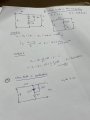
This is another circuit which i am trying to solve, i have few questions please help to clarify

My work is as attached,
Q1. When the diode is non conducting which method do i need to use to calculate i(t)?
Q2. At exactly 3.7V of the input voltage, the diode will not start conducting, how to calculate the exact value at which point it will start conducting?
My work is as attached,
Q1. When the diode is non conducting which method do i need to use to calculate i(t)?
Q2. At exactly 3.7V of the input voltage, the diode will not start conducting, how to calculate the exact value at which point it will start conducting?
Attachments
-
 96.3 KB Views: 13

")


