Electret mic with LM386

Thread Starter

salvus

Joined Apr 2, 2020
49
Hi,

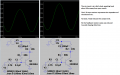
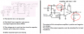
I am interested in making a simple mic amplifier circuit. I have just copied what is in this youtube vid but I have used an
CMEJ-0627-42-SP electret mic, it's one I just had lying around. When I play tones with my phone I can make out the waveform on the oscilloscope but it is not as good as the results seen in the video and the phone has to be very close. I have tried a few different preamplifier circuits before the LM386 stage but this didn't seem to make much difference or was actually worse. I am thinking that I might need a different mic. I don't have much electronics experience so that might well be very obvious just from looking at the datasheet. Can anyone recommend what model would be a better alternative? The budget is anything around the few dollars mark, ideally, I do not want a premade board from something like Sparkfun. What is it that I need to look out for when buying an electret mic to make sure it will give the best output?

Thanks for any help and suggestions
 

Audioguru again

Joined Oct 21, 2019
6,673
Why do you copy a circuit shown on You Tube that is completely wrong?
Its author did not look at the datasheet for the LM386 and did not lookup an electret mic in Google.

1) The electret mic MUST be powered with a resistor from a filtered DC source.
2) The datasheet for the LM386 shows some very important parts that are missing in the video.
3) A breadboard has rows of contacts and wires all over the place that are antennas that pickup hum, buzzing and all kinds of interference. The parts should be soldered onto a small circuit board. Very short wires or a shielded audio cable should connect the mic.
Look here:
 

Attachments

Irving

Joined Jan 30, 2016
3,843
There's nothing wrong with the mic... Look at the datasheet for it. It needs at 2.2k load and that 0.01uF capacitor is far too small. At 1kHz that 10nF capacitor has an impedance of 15k... no wonder its not working! Try this version...

EDIT: AG beat me to it! His attachment shows a slightly more complex arangement. I've used the LM386 without the output compensation (.05u + 10R) and it works fine, but it'll depend on the quality of your layout. The size of the DC bypass capacitor C4 will depend on your 5v supply and what else is running on it you may need more (100uF up, with a 100nF in parallel)

1602364460919.png
 
Last edited:

Audioguru again

Joined Oct 21, 2019
6,673
Irving, your 10uF input capacitor will pass 0.32Hz earthquake frequencies into the 50k ohms input of the LM386 amplifier.
But 0.1uF will pass audio frequencies down to 32Hz which is probably low enough.

Your 5k gain control goes not reduce the gain much. There will probably be acoustical feedback howling even when the gain is turned down.
 

Irving

Joined Jan 30, 2016
3,843
Agreed the 10u might be overkill; it is 1u in the mic data sheet but 0.1u would work OK too.

Not sure why you think the gain control won't work? Its the approach given in the LM386 datasheet and one I've used before. About 1k will give a gain of 100, 1v pp out for that mic (approx). Unless you were thinking to reduce the gain below 20, which can't be done like that. By why would you want to reduce it? The mic is -40dB so needs a fair amount of gain to be useful. I've not found the LM386 to be particularly unstable though it wouldn't be my first choice for a mic pre-amp.
 

Thread Starter

salvus

Joined Apr 2, 2020
49
Many thanks for your help and advice. So far I am not having much luck with those circuits. I am indeed just using a breadboard so that will be the next thing for me to change. Why is the LM386 not ideal? Is it not specifically designed for this purpose? I have the following op-amps on hand, is there any that you think would do the job well?

LM324N 6183Y
TBA820M
JR23AFE3 LM 741CN
18MDSHY TL082CP
41A17FM TL084CN

Thanks again, much appreciated
 

Irving

Joined Jan 30, 2016
3,843
Try the circuit I suggested with TL082, though both TL072 and TL082 both might struggle on only single 5v supply. LM324 (different pin-out) will work ok on 5v but isn't as good an amp.

LM386 is a power amp and is often used for driving small speakers or headphones. It's too noisy to be a good pre-amp.
 
Last edited:

Audioguru again

Joined Oct 21, 2019
6,673
Yes, I agree, thats one reason it wouldn't be my first choice... almost any op-amp would be a better option, something like this...

View attachment 219297
I have used many TL072 audio opamps. They do not work when the supply is only 5V, 7V is the minimum but the datasheet recommends at least 10V.
You use the voltage across the mic to bias the opamp but since the electret mic draws 0.5mA then in your circuit it gets only 1.1V and the opamp input is also at only 1.1V.
In your single-supply circuit, the minimum DC input voltage for a TL072 is 3V to 4V and if it is less then most of them show the Opamp Phase Inversion problem that causes its output to go to a voltage as high as it can and not work properly
 

Attachments

Irving

Joined Jan 30, 2016
3,843
@Audioguru again Yes, you're right. I took 2v as the supply voltage not the value at the mic pin. The 5k6 resistor should be a 3k6, which will bias the mic & opamp at 2.1v

I did say the TL072/082 would probably struggle at 5v, but I thought worth a try. However, I'll happily bow to your better experience on that. The LM324 is good down to 3v but noisier and much lower input impedance, though not so low as to be a problem. Should be better than the LM386 though. There are many dual low-noise opamps with the same pinout as the TL072/82 that'll run happily on 5v eg OPA2132, just the TS doesn't have anything to hand.
 
Last edited:

Thread Starter

salvus

Joined Apr 2, 2020
49
I am still struggling with this. I have also tried just using a transistor using the following circuit but the result of that seemed to make no difference from just looking at the signal directly from the mic. I think I will have a go with the LM386. If I were to order a new electret mic and amplifier, which would your top choices be? I am looking for something around the few dollars mark with a small physical size. Thanks again :)
 

sghioto

Joined Dec 31, 2017
5,379
I am still struggling with this.
Why is that? Before you go changing mics and chips get the LM386 circuit working that AG showed you in post #2. If your breadboard and/or wiring is the problem then new mics and chips won't make any difference.
Post a photo of the breadboard with the components installed and maybe we can see what is not working correctly.
SG
 

Audioguru again

Joined Oct 21, 2019
6,673
In my post #2 I show the completely wrong circuit you found and I added corrections to it. Then when built on a pcb it works perfectly.

Now I show a simulation of the transistor circuit and it works fine when the 100k resistor is reduced to 68k to avoid clipping distortion.
The 10k resistor that powers the mic must be reduced to about 330 ohms for the mic to work when the supply is only 3V but that reduces its output level a lot.
The transistor has an input level of 30mV peak and an output level of 550mV peak, the difference is 18 times more.
 

Attachments

Top