 Facebook
 Google
 GitHub
 Linkedin
Hello,
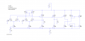
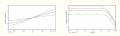
I designed DVCC Instrumentation Amplifier with LTSPICE XVII. I used 0.18um Technology for FETs. The file is attached. When i simulate it i can take a good graph for DC characteristic but my frequency response seems wrong. Is there anyone who could help me. My Circuit and simulation results are attached.
I designed DVCC Instrumentation Amplifier with LTSPICE XVII. I used 0.18um Technology for FETs. The file is attached. When i simulate it i can take a good graph for DC characteristic but my frequency response seems wrong. Is there anyone who could help me. My Circuit and simulation results are attached.
Attachments
-
 24.1 KB Views: 28
 -
 26.3 KB Views: 23
 -
 28.5 KB Views: 20
 -
 48.9 KB Views: 18
 -
 49.6 KB Views: 19
 -
4.9 KB Views: 13


