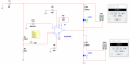
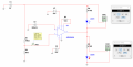
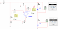
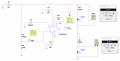
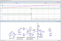
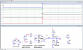
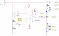
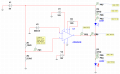
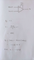
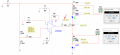
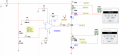
May I know what's the explanation behind the "D1 LED" and "D2 LED" lighting up differently when the LM35 is below 0.5V and above 0.5V?
My understanding:
1. When the LM35 is below 0.5V, the Vo is in positive value thus overcoming the forward voltage of the "LED D2" and lighting it up.
2. When the LM35 is above 0.5V, the Vo is in negative value, thus not able to overcome the forward voltage of the "LED D2" and not lighting it up. During this period, the voltage of 5V connected in series to "LED D1" is lighting it up.
3. Or should I observe the current value passing through "LED D1" & "LED D2"?
4. For the AD620 IC at the above circuit, I saw that the Rg pins are connected to 10ohm resistor. Is there a reason? the difference between shorting it and connecting a 10 ohm resistor?
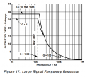
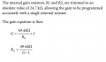
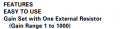
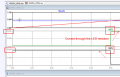
If i observed the graph, I can observe the gain is upto 1000 only. If i were to put 10 ohm resistor at the Rg pin 1 & pin 8. Theoretically, through calculation the G = (49.4k/10) + 1 = 4941.
Can I assume the AD620 chip limit the gain to 1000 only?
The AD620 is acting as a Comparator and the Vout switches over at the Vref versus Vtemperature voltage point.
4. For the AD620 IC at the above circuit, I saw that the Rg pins are connected to 10ohm resistor. Is there a reason? the difference between shorting it and connecting a 10 ohm resistor?
2. When the LM35 is above 0.5V, the Vo is in negative value, thus not able to overcome the forward voltage of the "LED D2" and not lighting it up. During this period, the voltage of 5V connected in series to "LED D1" is lighting it up.
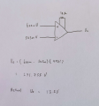
When I detached the connection of AD620 output from the LED, the output voltage value is different:
Vtemp < Vref: Vdc = -14.0
Vtemp < Vref: Vdc = 13.8V
If I were to understand it, because the AD620 is used as a comparator. The output voltage value would be saturated towards the supply voltage +15 & -15.
What happens to the voltage value of the output of A620 when it is connected to the two LEDs?
If i refer to the gain equation and the maximum gain limit given in the AD620 datasheet:
The Rg should be less than 49.45 ohm to achieve maximum gain. The reason I said this is because if I would like AD620 to act as a comparator, the gain would be amplified to ensure the output voltage reaches saturation at +15V or -15V if refer to my constructed circuit.
hi Isaac,
With a Rg of 10 ohms and the Gain Equation, that is a Gain = 49400R/10R = 4940.
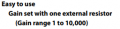
Which is roughly half the maximum gain stated in your second data clip of 10,000 and 5 times greater than the first data clip of 1000 maximum.
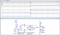
If you are confident that the second link is correct, you could use a 5R for RG, which gives a gain of ~10,000, attached simulation.
I have increased the LED resistors for the LED's to 1k5, this will give an LED current of approx 10mA which is OK.
hi Isaac,
With a Rg of 10 ohms and the Gain Equation, that is a Gain = 49400R/10R = 4940.
Which is roughly half the maximum gain stated in your second data clip of 10,000 and 5 times greater than the first data clip of 1000 maximum.
If you are confident that the second link is correct, you could use a 5R for RG, which gives a gain of ~10,000, attached simulation.
I have increased the LED resistors for the LED's to 1k5, this will give an LED current of approx 10mA which is OK.
My laboratory is only able to provide the smallest resistor value of 10ohm, unfortunately. So I'll stick with 10 ohm resistor as your previous LTspice simulation circuit.
May I know how did you manage to produce the current value of 18mA & 10mA from the two graphs of both your LTspice simulation?
How can I control the current value passing through the two LEDs? Is it through connecting a different value resistor? Is there a way to calculate? Ohms Law?
How can I control the current value passing through the two LEDs? Is it through connecting a different value resistor? Is there a way to calculate? Ohms Law?
hi,
May I ask what technical course you are enrolled on and at what year level you are studying.?
I ask this in order to know at what level I have to explain my help.
Calculating the current through a Series resistor and LED are very basic equations.
E
hi,
May I ask what technical course you are enrolled on and at what year level you are studying.?
I ask this in order to know at what level I have to explain my help.
Calculating the current through a Series resistor and LED are very basic equations.
E View attachment 281926
Hi, I'm currently enrolled in BSc in Electrical & Electronics Engineering, 2nd year of studies.
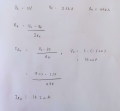
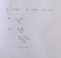
If I were to calculate the current passing through the resistor, R1 would be:
V = IR
- V = ? [AD620 output after differing the voltage value between (+) & (-) terminal] *I dont get this part*
- I = ?[I am finding this value]
- R = 1k ohm
I(R1) = V/1k
= ?
______________________________________________________________________________________________________________________________________
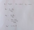
If I were to calculate the current passing through the resistor, R3 would be:
V = IR
- V = 5V
- I = ?[I am finding this value]
- R = 1k ohm
I(R3) = V/R
= 5/1k
= 5mA *This is not tie-in to the value from your graph*
Hi Isaac,
When driving an LED you must consider the forward voltage drop across the LED.
eg: Assume the LED is a Red type with a forward voltage drop of 2V and the supply is 5V, and we require 10mA through the LED.
Rser= (5v-2v)/0.01A , > 3V/0.01A = 300R.
Note: different coloured LED's have their own forward voltage drop, always refer to the datasheet.
- V = ? [AD620 output after differing the voltage value between (+) & (-) terminal] *I dont get this part*
- I = ?[I am finding this value]
- R = 1k ohm
The Vout terminal of the AD620 can either Source or Sink current at the junction of the LED's/Resistors network.
The AD620 Source/Sink current has to be considered in your calculations as well as the current from the +5V voltage source.
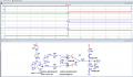
Added: Sim showing the AD620 Vout Source and Sink currents, I(V5) plot and the LED currents.
The Vout terminal of the AD620 can either Source or Sink current at the junction of the LED's/Resistors network.
The AD620 Source/Sink current has to be considered in your calculations as well as the current from the +5V voltage source.
Hi Eric, I am not clear regarding this part. I am trying to understand how the AD620's Vo of "10.2V" & "-5.22V" from my simulation circuit came to be.
My current understanding is that because the Rg inserted to AD620 is 10ohm. The Vo of AD620 is saturated towards the supply voltage(+15V & -15V). From my circuit, I'm getting +13.5V & -13.7V which I can consider theoretically correct?
My current understanding is that because the Rg inserted to AD620 is 10ohm. The Vo of AD620 is saturated towards the supply voltage(+15V & -15V). From my circuit, I'm getting +13.5V & -13.7V which I can consider theoretically correct?
Hi Isaac,
This LTSpice sim plot shows the Voltage on Vout for both saturation levels, also the currents flowing in the Resistor/LEDs.
I have chosen 1k5 resistors in order to reduce the current loading on the AD620 output.
If you consider in the positive Saturation State that you have +13.5v across R1/D2 and in the negative saturation you have +5V at the high end of R3 and –13.5v at the lower end, a total of 18.5V across R3/D1.
Compare your calculations with this plot
The Vout terminal of the AD620 can either Source or Sink current at the junction of the LED's/Resistors network.
The AD620 Source/Sink current has to be considered in your calculations as well as the current from the +5V voltage source.
While referring to my calculations made for I(R4) & I(R3), I am wondering about the voltage value of Vout terminal of the AD620.
1. When the Vout terminal is not connected to the LED part of the circuit, the Vout would be +13.5V & -13.7V. [I understood this one from your earlier reply, thanks]
2. When the Vout terminal is connected to the LED part of the circuit, the Vout would be +9.62V & -5.22V. [I am not clear on this part]
Is it because of "Current source" & "Current sink"? If I were to understand these 2 terms would be this way:
Or is it because of resistors and LEDs present after being connected to the AD620 output?

 Facebook
 Google
 GitHub
 Linkedin