Dual temp LCD display

Thread Starter

1-3-2-4

Joined Dec 26, 2008
199
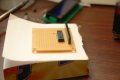
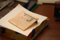
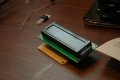
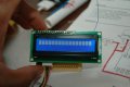
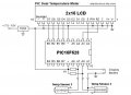
I'm building a dual temperature display from a kit but I have a question with the PCB I want to make it neat since it will all be going in a project box.. I'm a little stuck on how to connect the pins from the PIC controller to the female 16 pin header.. do I just solder from the PIC to the female header?

picture of the schematic is here
 

Attachments

beenthere

Joined Apr 20, 2004
15,819
You say you're working on a kit. Doesn't the PIC go on the PCB and aren't there traces from the PIC to the LCD socket? That is pretty standard.
 

Thread Starter

1-3-2-4

Joined Dec 26, 2008
199
I have a generic PCB left over but what had me confused (and I checked multiple times to make sure I'm right) how the PCB should be and the header mounted to the PCB just that the PIC i had to turn the other way to get Pin 1 to point the same way as pin 1 for the LCD. I was doing a solder bridge I already did Pin 1 of the PIC and pin 2 which connect to the header to the right spots. However I need to do the ground for Pin 1 and pin 16 which also connects to (-) on the PIC I can't do a bridge with that.. Would a wire be ok here? I just want the connection to be solid because this will be put in a car. Also i'm a little confused with the voltage regulator it's a part number LM7805C What do I use as power input leads for this?
 

Attachments

Last edited:

Thread Starter

1-3-2-4

Joined Dec 26, 2008
199
after taking a few breaks and running out to find some extra parts I finished.. however when I turn the power on all I get is a row of blocks seen here.

Any tips why this is happening?

*edit hmm might be that I forgot to connect D7 up to the LCD when I went to clean up.

nope still not working just showing blocks
 

Attachments

Last edited:
Top