Facebook
 Google
 GitHub
 Linkedin
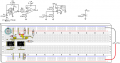
I've known for a while op amps in general have problems with inputs near or at the power supply. I decided to run some formal experiments to see what these limits are. I've also run into problems with earlier designs. So I am going to run a series of experiments using a 1458, LM385, and 4565 dual op amps. I will be using a 555 circuit to input a square wave. I finally settled on a 555C timer For all the experiments , reason being it was a little bit more stable on my oscilloscope. I found out using an old 555 FD bypass cap it's not just important but the location of the cap is too. The inductance on the line there protoboard was enough to cause some apparent jitter which was an artifact. This is why C4 a 220µF capacitor was put in such an odd location. For the moment I will just post the data . I will speculate why the outputs were the way they were in the following posts.Feel free to add your 2¢. I would be glad to rerun any experiment if asked. I will also include a picture of the circuit if asked.
555 / 555C signals


.............555....................................555C
Experiment 1
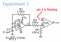
Schematic/Layout
[/COLOR]4565
Waveforms


…...........1458…...........………….LM385…...........………….
555 / 555C signals
.............555....................................555C
Experiment 1
Schematic/Layout
[/COLOR]4565
Waveforms
…...........1458…...........………….LM385…...........………….
Last edited: