Dual micro switched winch contol

Thread Starter

MacGyver01

Joined Jul 17, 2024
12
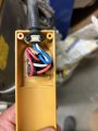
I am using a hoist motor to control a prototype piece of equipment that rotates 180 degrees clockwise, 180 counter clockwise and repeats stopping at both rest points. The motor has one micro switch already which stops the travel yet allows the motor to reverse. This intended to stop the load hook from going into the cable spool.
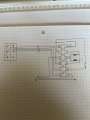
I would like to have a second switch for the opposite direction with the same function, stops rotation but allows for reverse travel.
I thought this might be achievable with the parts available but now am thinking it might be more involved. Has anyone done this or can share how to achieve this?
 

Attachments

Thread Starter

MacGyver01

Joined Jul 17, 2024
12
I am rotating a cage for flipping spools of pipe. I am using the winch because it has the power and speed I need and runs on 110v which is all I have available in the location this will be used. It is also very cost effective.
If the second switch is not easily done we will look at other options.
 

Jerry-Hat-Trick

Joined Aug 31, 2022
776
I think you should be able to wire the motor with a DPDT (Double Pole Double Throw) switch to make it go in opposite directions. At each end of travel wire a normally closed microswitch to open that circuit. I'd recommend another rocker/toggle switch to connect/disconnect power and maybe an emergency stop switch. You can get DPDT switches with a central off position but I think a separate power switch is safer
 

LowQCab

Joined Nov 6, 2012
5,101
Mechanical-Safety is far more important than "how do I wire-it-up".

I think it might be a good idea to double-up (4) on the Micro-Switches, ( connect 2 in series ),
as well as making sure that the Micro-Switches can not be crushed or otherwise mangled from
any inadvertent/accidental over-travel.

There must be substantial steel-stops to prevent any over-travel in either direction.

There must be some method of maintaining a minimum amount of tension on the Cable.
A loose Cable can easily create a huge mess out of everything.

If the Limit-Switches are not properly adjusted, or
the Circuit, for some reason, fails to work as expected,
and the Cable gets too tight,
things could break and go flying in a rather spectacular and violent way.
So make sure you're not standing in the wrong place if this happens.
.
.
.
 

Thread Starter

MacGyver01

Joined Jul 17, 2024
12
Mechanical-Safety is far more important than "how do I wire-it-up".

I think it might be a good idea to double-up (4) on the Micro-Switches, ( connect 2 in series ),
as well as making sure that the Micro-Switches can not be crushed or otherwise mangled from
any inadvertent/accidental over-travel.

There must be substantial steel-stops to prevent any over-travel in either direction.

There must be some method of maintaining a minimum amount of tension on the Cable.
A loose Cable can easily create a huge mess out of everything.

If the Limit-Switches are not properly adjusted, or
the Circuit, for some reason, fails to work as expected,
and the Cable gets too tight,
things could break and go flying in a rather spectacular and violent way.
So make sure you're not standing in the wrong place if this happens.
.
.
.
I a not using the cable, the drum is removed and tied to a gearbox. The rotation is very slow for control. The part that triggers the switch is on a spring load. I thought of mechanical stop however this could create tension and a catastrophic failure whereas if the machine simply rotates to far an air hose could come disconnected.
two switches is fair.
 

MisterBill2

Joined Jan 23, 2018
27,164
OK, aside from safety warnings, already delivered, reversing a n AC-mains powered motor is a bit more complicated.
Since the motor was for a winch application there must already be some scheme for making it run in both directions. That arrangement is what we would need to understand to be able to suggest a means to provide the requested control method.
No additional safety warnings from me yet.
 

vu2nan

Joined Sep 11, 2014
357
It's presumed that it's a single-phase, capacitor-run hoist motor.

A single-pole, two-way, centre off momentary selector switch should suffice.

Here's the schematic.

Untitled.png

Nandu.
 

MaxHeadRoom

Joined Jul 18, 2013
30,558
It's presumed that it's a single-phase, capacitor-run hoist motor.
A single-pole, two-way, centre off momentary selector switch should suffice.
Here's the schematic.
That is what I was alluding to in my post, but that only works if it is a PSC (permanent Start Capacitor motor) with start & run windings that are equal, usually lower than 1HP , i.e. 1/2 to 3/4.
 

MisterBill2

Joined Jan 23, 2018
27,164
Some winch motors, and many hoist motors, have an internal brake that applies when the motor is not powered.
And I would much prefer to hear from the TS as to what type of motor it is..
In the first post it is a hoist motor, which would have a brake, then it became a winch motor, which is not under the same rules as a hoist motor. And it seems that the present application is neither winch nor hoist. That very crude drawing looks a lot more like a hoist control.
 
Last edited:

MaxHeadRoom

Joined Jul 18, 2013
30,558
@MacGyver01 I see by the 'very' crude drawing in post #1 the motor has two caps, apparently in parallel.
Can you post any documentation supplied with the original winch?
Motor info, schematic etc
 

Thread Starter

MacGyver01

Joined Jul 17, 2024
12
I will see what details I can find on the motor. I did not see the reply’s piling up. Thanks for the input, I will be back on this Monday. Have a good weekend folks.
 

Thread Starter

MacGyver01

Joined Jul 17, 2024
12
Sorry for the mixed names, this is a hoist but I don’t see a brake or magnet anywhere. It is light duty so I am thinking it is just very high gear ratio. I will clean up my schematic as well. The white board was just for thought process.
 

Attachments

MaxHeadRoom

Joined Jul 18, 2013
30,558
There appears to be a gear reduction, then a worm gear involved, if so, so worm drives cannot be back-driven.
I see the device is Power Fist, sold by Princess Auto in Canada. !
 

MisterBill2

Joined Jan 23, 2018
27,164
OK, based on the yellow motor connections shown and the view of the switch control, it does appear to be a PSC motor, so probably the original switch connections made to a DPDT, center off, switch should work out well. I did not see any worm drive part in the assembly drawing, but a double reduction spur gear arrangement.
It is quite interesting to see a hoist mechanism re-purposed for something else. Is this a "one-off" machine or a product prototype? It seems rather unusual.
 

Thread Starter

MacGyver01

Joined Jul 17, 2024
12
Correct on the point of purchase, similar hoists are sold through harbour freight. This is a one off unit built in house, we do a lot of custom equipment as our process is unique.
I have a cleaned up schematic based on the existing wiring. I thought I could switch line 10 but have no reverse function. I think I loose my capacitor so not enough power.
I know just enough to be dangerous and appreciate your guys input.
 

Attachments

MisterBill2

Joined Jan 23, 2018
27,164
There are just a few connections to the terminal strip that need to be changed, and possibly a change at the switch.
I am guessing that you want one switch for RUN/stop, and another switch for direction selection. That is possibly safer that a three position center off, run forward/run backward switch. Or maybe not. Either way is possible with what you have.

Probably you need to get the person responsible for product safety into the discussion.
 

Thread Starter

MacGyver01

Joined Jul 17, 2024
12
After some discussion with saftey and maintenance we would ideally have a foot switch for initial power, this will be mounted a few feet from the unit. As a secondary would still like a switch that has to be held down by the operator rather than allowing the machine to operate on its own. I think the switch on the pendant suits that need if it can be utilized. This gives distance, 2 switch operation that prevents accidental initiation.
 

Thread Starter

MacGyver01

Joined Jul 17, 2024
12
I am still stalemated on a solution for this. I would think I switch the #10 wire and seperate the top poles in the switch however not sure where to introduce the capacitor power or return capacitor power from the left side of the switch. Am I on the right track?
 
Top