 Facebook
 Google
 GitHub
 Linkedin
Thanks again for your patience and explanations. I really do appreciate it. I was actually thinking more along the lines of modifying the signal at the actual fuel injectors, rather than ECU inputs. The various inputs that can be tweaked on my vehicle (for the most part) I have already done.( i.e. ECT, IAT, MAF(both signal and load). If I can find a way to let the processor call for what it needs, but modify the ECU's output pulse rate sent to the injectors, I will be able to set my actual fuel delivery to whatever I desire. What are your thoughts (other than possible engine damage-which we BOTH know can and will occur if not properly instituted) on varying pulse width at the injectors in this manner?
Dual Lambda Signal Modifier
- Thread starter Capt-Killjoy
- Start date
Scroll to continue with content
That's a hard way to go. You might as well replace or re-map the entire ECU at that point. By directly modifying the injector PW output from the ECU, you'll essentially be taking over the ECU's job.
With a wideband lambda sensor, you can set any air/fuel ratio you want, and do so pretty accurately - as long as the ECU is operating in closed-loop mode. Of course, once you do something to get it out of closed-loop mode (like stomping on the loud pedal) you will be running on the default map.
Seems to me that projects like this really call for an ECU with multiple maps in it. I'm not up to speed on recent ECU developments. GM apparently has done something like this with their multiple-fuel vehicles - that's a guess, of course, but I can't think of how they would do it otherwise.
Vehicle manufacturers were pretty much forced to use stochiometric air/fuel ratios in order to minimize emissions and maximize the life of the catalytic converters. If you run the engine very far off the 14.7/1 ratio, you'll carbon them up or overheat them.
Introducing "HHO" into an engine with instrumentation/controls designed for running on just gasoline throws things considerably out of whack. Preignition due to possibly increased flame speed could be a real problem. Internal cylinder temperatures and pressures may be increased, and EGT may be lowered. The lowered EGT may interfere with the operation of the catalytic converter as well as the lambda sensor.
Much of this is speculation on my part. I simply don't have enough good information.
31 years ago, NASA did a study on running a 1969 Cadillac 500 cubic inch V8 with a mix of hydrogen/oxygen and gasoline. You can download the report here:
http://ntrs.nasa.gov/archive/nasa/casi.ntrs.nasa.gov/19770016170_1977016170.pdf
Wiki has an entry which appears to be objective (on an initial cursory examination):
http://en.wikipedia.org/wiki/Hydrogen_fuel_injection
Objective data with a scientific approach is what we would like to see. The NASA report is a bit lengthy, and I wouldn't expect a report here to be quite so verbose and detailed. However, it is a good model for objective and scientific reporting.
My speculations/extrapolations in my prior post may or may not be accurate. I am not an "automotive guru"; my typical projects involve items that are designed to exceed Mach 1 by a good margin. However, I'm no slouch in the "shadetree mechanic" arena either. Getting vintage Jaguar V12 engines purring like kittens is no mean feat, whether they are carbureted or FI.
My speculations/extrapolations in my prior post may or may not be accurate. I am not an "automotive guru"; my typical projects involve items that are designed to exceed Mach 1 by a good margin. However, I'm no slouch in the "shadetree mechanic" arena either. Getting vintage Jaguar V12 engines purring like kittens is no mean feat, whether they are carbureted or FI.
Thanks for the post from NASA. That experiment actually took place in my old home town of Albuquerque, NM at the AFB where my father was stationed.(Kind of ironic to me) I couldn't really ascertain from the report whether the experiment was a good thing or not. Had some good things and some bad from what I was able to discern. The hydrogen injection they were doing was straight hydrogen(unless I mis-read) which is considerably different from Brown's Gas or Hydroxy. But excellent data none the less. As for your expertise.....it became evident to me on our first postings that you had some experience with automobile technology which is why I have stuck w/you in most of my posts. Not to slight any other members, but I look for intelligent comments and comments based on facts, not here-say. And you have continually provided me with those intelligent conversations and I thank you for it. New ideas and different points of view constructively presented forward progress where simply bashing an idea is totally counter-productive(IMHO, that is) As for taking over control of the ECU by modifying my injector pulsewidths is exactly what I would like to do, but not having the resources to buy a stand-alone processor set-up causes me to seek alternative methods. BTW....any chance there are any computer gurus out there who can (privately) tell me a work around to reprogram my own ECU's parameters? I hadn't bother to post that request yet as I doubt I will get any takers, but who knows. I am in the process today of trying to find a suitable op-amp for the circuit you gave me. Will keep you posted on how things work out. Please feel free to stay in touch and I will send you data updates and progress if you are interested.
One final note.....on my original circuit that I showed on my second post.....what did I do wrong? I figured that I must have had a resistor(s) value wrong, but was just curious about where I went wrong. (Always trying to learn new things, you know...LOL)
One final note.....on my original circuit that I showed on my second post.....what did I do wrong? I figured that I must have had a resistor(s) value wrong, but was just curious about where I went wrong. (Always trying to learn new things, you know...LOL)
Last edited:
Isn't the Ranger actually made by Mitsubishi?
You can get "tuners" for Mustangs, F150/F250 trucks, but I haven't seen a tuner specifically for a Ranger.
Here's a brief article on Mustang tuning via the ODBII port vs replacing the chipset:
http://www.tuningmag.net/?name=tuning-the-ford-mustangs-ecu
I don't know how many profiles you can store in a Ranger ECU. However, you're going to need different maps for when you're running with your hydroxy system and on just plain gasoline. Variation in H2O2 flow from your cell will likely cause problems. More accurately stated, variations in the ratio of H2O2 to fuel/air will likely cause problems.
Just about all of the designs I've seen floating around the web use a H2O2 cell gas generation scheme that results in a somewhat constant flow of gas from the cell. That's fine for if the only driving you do is cruising at a set speed with a set load on level ground with no wind. However, if your cruising speed changes (say, from 30mph to 65mph) you're going to have far less H2O2 to fuel/air if you have a constant gas generation rate.
Your ECU is automatically adjusting the fuel/air ratio each time the injectors fire. But unless you have your H2O2 generation rate tied in to your air/fuel flow rate, you won't have a consistent mix. This could lead to some pretty strange-looking ECU curves.
It would probably be helpful to know what kind of flow rate your're getting out of your cell(s), even for just the baseline aspect. One of our members here mentioned using a water-filled piece of clear tubing in a "U' shape, and using an IR LED and phototransistor or photodiode to count the bubbles as they went past, which is definitely a possibility. You should already have something like that built into your system as a flame arrestor anyway; this would just be adding to it.
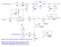
Capt-Killjoy, in case you need it, here is a circuit that should allow you to vary the clip level on the lower 0.5V of the input range, as I mentioned previously. I'm sorry it's so late, but I was out of town, away from my computer.
Attachments
-
 33.8 KB Views: 133
 -
 42.4 KB Views: 102
The Ford Ranger isn't a Mtsu product, however the Mazda pick-up also by Ford, is. FoMoCo has some pretty strange combinations like that. Most are the same with a different name and a few more goodies on the menu, but then you have some like the Ranger/Mazda trucks and the Windstar(Freestar now) and the Villager which are each two completely different breeds. As for the output of my current cell (another build currently underway for much bigger cell with variable output), I run approximately 2 lpm by my measurements. HOWEVER.....I don't consider filling a 2 liter soda bottle underwater a reliable method of calculation. It is only a rough guess, at best. I was more concerned that the cell output was steady rather than the actual measured output. I have been looking for a reasonably priced (precision) flow-meter but have been unable to find one that is calibrated to measure the flow of hydrogen. I would think (please correct me if I am wrong) that the hydrogen, being a lighter gas than oxygen, would not be accurrately measured in an oxygen flow meter, correct? If it would be the same I can get a flow meter from the local hospital supply and give you a more accurate reading. I do (of course) have a bubbler on my system (2 in fact) so the IR counter might be able to be incorporated as well if necessary. My latest cell will (hopefully) be capable of much more production (upwards of 15 liters per minute) if all goes well. This cell's output will be controlled both manually (for a preset level) and through using the 0-5v TP signal fed in as a trigger to my PWM to increase production as needed. I know this isn't really the best way to do the mix, as so many different variables come into play( i.e. load, BARO, temp, etc...) but I figured that TP encompasses MOST of those variables and it will be a place to make a modest start. Keep in mind I am only utilizing this for supplementation at this point. I believe I have figured out a method to allow me to run straight hydroxy with my new cell and a re-timed switchable crankshaft position sensor, but I don't think I will be able to do it at any other time than at cruise. Something to shoot for though.
And Ron H----thanks for the circuit, and no problem about the timing as I have been very busy myself.
And Ron H----thanks for the circuit, and no problem about the timing as I have been very busy myself.
Last edited:
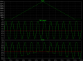
Ron H's circuit:
I edited his plots to add red reference lines at 450mV for the input and output signals, which is the trigger point for the ECU. Remember, the ECU isn't looking for an absolute level of 450mV, but transitions across the 450mV threshold. The lambda signal is actually much closer to a triangle wave than a sine wave, but I didn't have a good sample of lambda output to use. It's fairly typical to use a sine wave to demonstrate circuit performance.
Notice that as the lower portion of the signal is clipped, the ratio of time spent below vs above the 450mV threshold is unchanged, until the clipping exceeds the 450mV threshold. At that point, the threshold is no longer being crossed, which will lead to ECU open-loop operation and CEL illumination.
The advantage of Ron H's circuit is that the problem of lambda drift due to EGT rise is eliminated. The disadvantage is that there will be no noticeable effect on ECU operation as long as the clipping occurs below the threshold.
")
Don't forget that the 100W of power for electrolysis is coming from an alternator that's driven by the motor. Alternators aren't 100% efficient either - not even close. But even if they were 70% efficient (being the optomistic sort that we are) you'd need about 143 Watts of power in for every 100W out. So, 19.5W - 143W = 123.5 Watts in the hole, and at this point all we're trying to do is keep the engine running.
Now if you could figure out a way to get 1000W of power output from 100W of power input, that would do it. Unfortunately, the laws of physics tend to hamper progress in this direction (let's just say, screeching halt).
Now there are plans out there for cells and electronics that claim over-unity production. Most of us on here are highly skeptical of such claims, and for good reason.
I edited his plots to add red reference lines at 450mV for the input and output signals, which is the trigger point for the ECU. Remember, the ECU isn't looking for an absolute level of 450mV, but transitions across the 450mV threshold. The lambda signal is actually much closer to a triangle wave than a sine wave, but I didn't have a good sample of lambda output to use. It's fairly typical to use a sine wave to demonstrate circuit performance.
Notice that as the lower portion of the signal is clipped, the ratio of time spent below vs above the 450mV threshold is unchanged, until the clipping exceeds the 450mV threshold. At that point, the threshold is no longer being crossed, which will lead to ECU open-loop operation and CEL illumination.
The advantage of Ron H's circuit is that the problem of lambda drift due to EGT rise is eliminated. The disadvantage is that there will be no noticeable effect on ECU operation as long as the clipping occurs below the threshold.
Oh yes, thanks for the correction. I couldn't remember offhand. I got the "M" part right though.The Ford Ranger isn't a Mitsu product, however the Mazda pick-up also by Ford, is.
That's certainly better than nothing! I don't think I'd want to fill up anything larger than a 2L thinwall plastic bottle with H2O2 due to the explosion hazard.As for the output of my current cell (another build currently underway for much bigger cell with variable output), I run approximately 2 lpm by my measurements. HOWEVER.....I don't consider filling a 2 liter soda bottle underwater a reliable method of calculation. It is only a rough guess, at best.
I'm not a chemist; I really couldn't give you an accurate answer. However, I suspect that a positive displacement type flowmeter would be accurate no matter which gas was metered, while a "floating ball" type may vary depending upon the gas being metered. Your idea of the 2L bottle falls in the "positive displacement" category, since you filled it up with water first, and the H2O2 displaced the water.I was more concerned that the cell output was steady rather than the actual measured output. I have been looking for a reasonably priced (precision) flow-meter but have been unable to find one that is calibrated to measure the flow of hydrogen. I would think (please correct me if I am wrong) that the hydrogen, being a lighter gas than oxygen, would not be accurately measured in an oxygen flow meter, correct?
What design are you using for the new cell?If it would be the same I can get a flow meter from the local hospital supply and give you a more accurate reading. I do (of course) have a bubbler on my system (2 in fact) so the IR counter might be able to be incorporated as well if necessary. My latest cell will (hopefully) be capable of much more production (upwards of 15 liters per minute) if all goes well.
OK. The TPS signal is quite linear from closed to WOT. The actual airflow through the throttle body is going to vary considerably, largely dependent upon the actual size of the opening and MAP vs BARO. Since the throttle is a disk being rotated in a cylinder, the TPS signal won't really be a very practical way of regulating gas production. When the throttle is transitioning from fully closed to partly open, there is a relatively large change in the size of the opening for a small change in TPS signal output. Conversely, when the throttle is transitioning from perhaps 80% open to WOT, the TPS signal changes by 20%, yet the change in the size of the throttle opening is quite small.This cell's output will be controlled both manually (for a preset level) and through using the 0-5v TP signal fed in as a trigger to my PWM to increase production as needed. I know this isn't really the best way to do the mix, as so many different variables come into play( i.e. load, BARO, temp, etc...) but I figured that TP encompasses MOST of those variables and it will be a place to make a modest start.
You're not going to be able to run it on 100% H2O2 without some sort of supplemental energy input, like perhaps a nuclear reactor. About the best you can hope for using straight "brute force" electrolysis is roughly 100W of power in for 65W of power out, or a net loss of 35%. ICE's are notoriously inefficient; if you're getting 30% efficiency, it's a good day indeed. Let's just ignore power loss in the drivetrain, wheel resistance to rolling, etc. for a bit. So, if you're putting in 100W of power at the cell, you're getting 65% x 30% = 19.5W out at the crankshaft, for a net loss of over 80%.Keep in mind I am only utilizing this for supplementation at this point. I believe I have figured out a method to allow me to run straight hydroxy with my new cell and a re-timed switchable crankshaft position sensor, but I don't think I will be able to do it at any other time than at cruise. Something to shoot for though.
Don't forget that the 100W of power for electrolysis is coming from an alternator that's driven by the motor. Alternators aren't 100% efficient either - not even close. But even if they were 70% efficient (being the optomistic sort that we are) you'd need about 143 Watts of power in for every 100W out. So, 19.5W - 143W = 123.5 Watts in the hole, and at this point all we're trying to do is keep the engine running.
Now if you could figure out a way to get 1000W of power output from 100W of power input, that would do it. Unfortunately, the laws of physics tend to hamper progress in this direction (let's just say, screeching halt).
Now there are plans out there for cells and electronics that claim over-unity production. Most of us on here are highly skeptical of such claims, and for good reason.
Attachments
-
 42.4 KB Views: 64
Last edited:
It is quite possible to build an electrolysis cell that has separated chambers for the anode and cathode plates. An electrolyte filled channel conducts current for the electrolysis. You can opt to let the O2 go off to atmosphere, and simply feed H2 to the engine. That way, nothing is explosive until inside the intake manifold.
That might be interesting, as one sceptical site I visited put forth the thought that the mileage increase observed (on the order of your 5%) might be due to the boost from the water vapor introduced by the bubbler. Running H2 and no entrained water vapor might show something.
Awfully generous of us to let you conduct the experiments.
Last edited:
To: beenthere
LOL.....Awefully nice indeed!. I will be sure and let you know the outcome of your experiment when I have some results. I wish I could say that I have an over-unity device, but I have not yet see one with my own two eyes. (Although there are several people who have claimed to have done just that.) Stanley Meyers supposedly drove around a dune-buggy on nothing but water for 4 years before his death and his circuitry and WFC was supposed to be in excess of 800% efficiency, but I personally believe that encompassed his entire design NOT just the electrolyser. Although several people have duplicated his electrolyser and electronics and can get massive hydrogen production for mA of input. I haven't heard any actual measurements (lpm) but just seeing some of the duplicates of his work start up tells me they are getting at least 2-3 times the output that I can get w/20amps. So I am not totally convinced that it can't be done.....but I reserve judgement until I can see it, touch it, and measure it for myself. Bob Boyce also has a unit (101 plate, 100 individual series cell electrolyser, coupled w/a PWM that puts out 3 different frequencies coupled together through a 6 inch torriodal coil. He uses an AC to DC converter to provide the power for the cell and supposedly gets in excess of 300% effeciency. It is supposed to be able to produce 100 lpm. That is the style cell I am building now, only a smaller version. In fact, once I get closer to completion, I will have some torroid questions for all of you.
To: SgtWookie
So instead of using the TP for the gating control of my PWM, what would you suggest using as a control signal. I hadn't thought about the tip-in throttle scenario, etc. but you are right. TP may not be a good controller after all. I guess my reasoning behind TP was that I had already tweaked my other ECU inputs as much as possible and figured that TP would at least give me the ramp up signal necessary to increase H2O2 production. And it will, but like you stated, only in a linear increase/decrease. Guess I will have to re-think that one. Any better suggestions? Nothing really simple comes to mind when I think of alternatives. Could a comparator of some kind be coupled between MAF and TP possibly, which could average the 2 and base the increase on a combination of TP and actual MAF?
To: All
Interested to hear everyone's thoughts on this. Just out of curiousity, have any of you looked at Stan Meyers circuit designs for his voltage intensifier circuit. If not, and I get a copy to post here, would you mind taking a look at it and tell me what I am missing? He supposedly runs a resonant circuit to his WFC which utilizes an isolated ground and he pulses rectified HVAC to his WFC until the dielectric of the water is about to breakdown. At which time the pulses stop and the 'spring-back' effect on the electrons causes them to dissassociate releasing H2 and 02. However, I have no idea how the find the electrical resonance of the inductive/capacitive circuit. I'm sure actual values would be necessary for calculations, but if anyone has an explanation of how I can calculate the proper resonant frequencies, I would really appreciate it. I find it rather humorous that most people believe Meyers was talking about acoustic resonance, and who knows, maybe it all plays a factor, but I tend to believe it was electrical resonance he was referring to. In particular LC resonance.
Last edited:
All of the resonance effects described on various internet sites contain mutually contradictory statements. I have looked over the "D9" pdf that hawks Bob Boyce's electrolyzer, and find it less than persuasive - http://forum.allaboutcircuits.com/showthread.php?t=14396.
My own take on the complexity of the several schemes makes it impossible to expect a duplication of the apparatus described. That makes the over-unity stuff basically a scam.
If anyone has actually sat down with a cell and done a recorded, reproduceable experiment to look for resonance effects in electrolysis, it hasn't surfaced on the internet. And, because so many devices use either multiple frequencies (in one case, orgone energy), negative results simply will not "prove" anything.
The constant worry about agents form the oil cartels suppressing data and buying inventors silence is pretty weird. Nobody seems to notice that all these sites are operating out in the open with no interference. Makes it hard to believe the suppression conspiracies. It probably makes it a bit unappetizing to look into experimenting.
Nobody has yet to be able to demonstrate results that are better than Mr. Faraday's from 1820. That's also a long time to maintain a conspiracy of silence.
I'm afraid my skepticism runs rampant when he's mentioned.Stanley Meyers
See why I'm skeptical?Although several people have duplicated his electrolyser and electronics and can get massive hydrogen production for mA of input.
Unless I'd inspected the whole test setup, my skepticism would remain.I haven't heard any actual measurements (lpm) but just seeing some of the duplicates of his work start up tells me they are getting at least 2-3 times the output that I can get w/20amps.
That's a tough one, because I don't know what an optimal ratio of H2O2 to fuel/air would be. By itself, it's a stochiometric fuel and oxidizer mix; but the primary goal isn't to act as a fuel; it's to increase the flame speed, but not to the point of causing preignition or detonation. Adding H2O2 to the fuel/air mix is different from just adding hydrogen.So instead of using the TP for the gating control of my PWM, what would you suggest using as a control signal.
However, I suppose that integrating engine RPM with MAP and BARO would be a good start.
It's a bit more complex than that. Something to sleep on.Could a comparator of some kind be coupled between MAF and TP possibly, which could average the 2 and base the increase on a combination of TP and actual MAF?
That was why I posted the question. I have been looking for someone with expertise in the electronic field to shed a little light on some of the info out there. Of course, IF there is something special about the way Meyers or Boyce are/were doing things, one would never really know for sure unless they built and tried it for themselves. I guess that is why there are so many people trying different things. I try to keep an open mind with regards to most things, even if some don't conform to the current laws of physics, but I am highly skeptical, as you are, of an over-unity electrolyser. I think there may be a way to add enough items to a vehicle to negate the current draw on the alternator and lower the load on the motor(i.e. totally separate power supply), but at what weight cost?! Doesn't seem to make much sense to me. I think the best way would be to take a Ford Hybrid Escape and rig a quasi-Bob Boyce (xxx)-cell unit to the HVDC output from the battery pack. That way the regenerative braking would constantly keep the batteries charged, and 330v should be able to produce enough hydroxy to start and run a 4 cylinder engine until the vehicle's systems could start the recharging process, I think. (Did I mention that I was Ford Hybrid certified also? This is another project I have been working on. So many projects, but so little time.)
I wouldn't call it over-unity in the least..just one huge brute force electrolyser! I think the electric car coupled with a hydrogen on-demand system shows more promise than trying to couple hydroxy gas into a gasoline engine as a supplement. My 5 mpg gain, I know from my own data, wasn't due solely from the addition of the hydroxy. The addition of the hydroxy only added an additional 3 mpg to the total, and I also wondered about the increase coming from the water vapor, but ruled it out as I tried running a second 'dryer' bubbler loaded with dessicant. My mileage stayed the same either way so I surmised the increase was actually due to the hydroxy. However, since I have found that 'sweet spot' that someone referred to in an earlier post, I fear my fuel savings on this particular vehicle have come to an end. If I run my cell at a higher amperage, I start losing MPG's fast due to the increased load on the alternator, which as I said before could be worked around if I wanted to make it's power source separate from the vehicle's. But more importantly, the timing of the motor is what prevents any further increase in savings. IMHO this is about as far as it can go unless the spark timing is retarded in unison with the addition of the hydroxy. More hydroxy=More retarded timing. And in order to be able to vary the timing to such a radical degree (for pure hydroxy running), and to keep it constantly variable over what could become a VERY wide range, just doen't seem plausable to me unless I build an engine, timed to be run on straight hydroxy. And if I am going to do that, then that effort will be made towards my Hybrid project, not a normal gasoline-powered vehicle. What are your thoughts on the power needed to make enoiugh hydroxy from the 330VDC battery in the Escape to start the engine and start the hybrid battery pack recharging?
I also find most of the conspiracy theories strange. I have been playing around with various different things for quite some time now, and no MIB have ever come knocking on my door. However.....IF a true replacement for fossil fuels ever WERE found.....I don't doubt for a second that any of the oil producing nations would do WHAT EVER IT TOOK, to suppress that technology from EVER being put into production. Can you imagine what that would do to the global economy if all of a sudden, nobody needed anybody's oil anymore? The ramifications are endless. So I don't rule out the cartel's taking action if it came to it, but nobody has anything worth getting worried about from what I've seen and proved/disproved. Don't know yet about the hybrid experiment though.....mebbe I should start censoring my posts.....shhhhh, I think they may be listening in.
Last edited:
You might as well just run on batteries. At least then there's no middle process that's wasting lots of power.I think the best way would be to take a Ford Hybrid Escape and rig a quasi-Bob Boyce (xxx)-cell unit to the HVDC output from the battery pack. That way the regenerative braking would constantly keep the batteries charged, and 330v should be able to produce enough hydroxy to start and run a 4 cylinder engine until the vehicle's systems could start the recharging process, I think.
Remember - brute force electrolysis is at best around 65% efficient - and then you have that ugly 30% efficiency of the ICE. Just those two processes, and you're already throwing over 80% of your energy right out the tailpipe.
Regenerative braking only helps a little.
If you really want efficiency, drain the fuel tank, and use an extension cord to keep the batteries charged.
I really hate to burst your bubble, but unless you can produce gas at a rate far past Faraday's prediction, you're going to have to add an external energy source somewhere to run on "hydroxy". A huge brute-force electrolysis cell just won't do it.I wouldn't call it over-unity in the least..just one huge brute force electrolyser! I think the electric car coupled with a hydrogen on-demand system shows more promise than trying to couple hydroxy gas into a gasoline engine as a supplement.
OK, that's useful. What was the original MPG?My 5 mpg gain, I know from my own data, wasn't due solely from the addition of the hydroxy. The addition of the hydroxy only added an additional 3 mpg to the total, and I also wondered about the increase coming from the water vapor, but ruled it out as I tried running a second 'dryer' bubbler loaded with dessicant. My mileage stayed the same either way so I surmised the increase was actually due to the hydroxy.
Water injection was used in WWII fighter aircraft like the F4U Corsair. The big 18-cylinder 2-stack 2,000HP engine had just a few minutes' worth of water injection to keep the cylinder head temps down while running at full emergency power, and reduce preignition.
You might notice that older vehicles run a bit better in the cool, damp morning air than later in the day. The cool air is more dense. Surprisingly, damp air is less dense than dry air, but in an older vehicle, the dampness will help a bit with the tendency to preignite if the cylinder head is carboned up.
Well, the solution for that is to connect a few cells in series, and use a buck-type constant current circuit. That is, if the cell design you have in use has alternating +/- plates and is using just straight PWM.However, since I have found that 'sweet spot' that someone referred to in an earlier post, I fear my fuel savings on this particular vehicle have come to an end. If I run my cell at a higher amperage, I start losing MPG's fast due to the increased load on the alternator, which as I said before could be worked around if I wanted to make it's power source separate from the vehicle's.
With straight PWM to reduce your current usage, you are reducing your average current, but the cell only generates gas while the current is flowing. So, you're alternating between no gas production, and too much current which generates gas but also wastes energy in heating up the electrolyte.
If you use a buck-type current regulator circuit, there is always current flowing through the cell, at an optimal rate that you set.
Controlled by the ECU, I suppose - no more distributor, right?But more importantly, the timing of the motor is what prevents any further increase in savings. IMHO this is about as far as it can go unless the spark timing is retarded in unison with the addition of the hydroxy. More hydroxy=More retarded timing.
There's that >80% loss in efficiency you'll have to deal with, just between the brute-force electrolysis and getting the engine running at idle. Remember what I wrote a page or so back? Basically, you're trying to create energy using "hydroxy" that you obtained via electrolysis. It ain't gonna work. Hydrogen is a carrier of energy. You put energy into a process to separate the hydrogen from oxygen, or methane reformation, or whatever other process you choose. The problem is, you don't get as much energy back when the hydrogen and oxygen are recombined during combustion.And in order to be able to vary the timing to such a radical degree (for pure hydroxy running), and to keep it constantly variable over what could become a VERY wide range, just doen't seem plausable to me unless I build an engine, timed to be run on straight hydroxy. And if I am going to do that, then that effort will be made towards my Hybrid project, not a normal gasoline-powered vehicle. What are your thoughts on the power needed to make enoiugh hydroxy from the 330VDC battery in the Escape to start the engine and start the hybrid battery pack recharging?
You somehow believe that you can build an over-unity gain perpetual motion machine. The closest thing we have to that now is our sun, and not even the sun is going to keep running forever.
I understand there are quite a few delusional paranoids around...I also find most of the conspiracy theories strange. I have been playing around with various different things for quite some time now, and no MIB have ever come knocking on my door.
It's used for a heck of a lot more than just oil, gasoline and diesel fuel. Most plastic products are petroleum based. The clothes you wear have petroleum-based material in them, unless you're wearing 100% cotton, wool or silk. So are most cosmetic items. If you have an asphalt driveway - that's petroleum; the stuff left over after refining. They even used to spray dirt roads down with used motor oil to keep the dust under control; I think that stopped in the 70's. Now they recycle it.However.....IF a true replacement for fossil fuels ever WERE found.....I don't doubt for a second that any of the oil producing nations would do WHAT EVER IT TOOK, to suppress that technology from EVER being put into production. Can you imagine what that would do to the global economy if all of a sudden, nobody needed anybody's oil anymore?
I don't think the oil-producing nations are worried about a drop in customer base. The Earth keeps becoming more and more populated, and all those people do a lot of other things with petroleum-based products than just put it in a gas tank.
The biggest problem with running a sraight electric car is the recharging aspect and the limited range before needing a recharge. Believe me, I don't have any delusions about being able to design a perpetual motion machine or an over-unity device....only that I would like to see a vehicle that would have an almost unlimited range without having to fill it up with fossil fuel. And you're right, fossil fuels are used for many things...but my focus is primarily the various fossil fuels. There will always be a need for petroleum products, but the statement I made concerning the cartel's jumping into action is based on the massive reduction of consumption that would take place if fossil FUELS were no longer in demand. Anyway, all different theories abound, and fossil fuels will always be around as the earth is constantly making more.
As for the further (or lack of) increase of my fuel economy, you were correct in that my 2005 Ranger has EDIS ignition (electronic-distributorless) so varying the SPARK timing is not an easy thing to accomplish without being able to change the actual ECU's programming. Some retardation can be accomplished by modifying the IAT signal, but the ECU will only retard the timing so much. And that is definatly not enough to allow me to get further gains as the added increase of hydroxy is creating resistance to the piston stroke. Not enough to cause any real damage, but creating enough resistance that the overall increase in fuel mileage rapidly decreases. I tried running my cell on a separate power supply all together since my last posting regarding this, and found that even though I eliminate the added load from the alternator, my mileage still won't increase with the additional hydroxy. Please keep in mind though that this test was only carried out on a short test (300 miles) and I like to run scenarios for at least 1000 miles before I make any (what I would consider) solid conclusions. As for my mileage information...my original mileage on my Ranger was 19.8 mpg without any modifications or hydroxy addition. My mileage went up by 2.1 mpg after modifying the IAT, ECT, O2 sensors, and MAF. Basically doing away with the majority of the cold start stradegy in the ECU, and forcing the ECU into thinking IAT was hotter than actuality. MAF was modfied to lower the calculated load slightly(but without sacrificing any noticeable performance). As I stated earlier, this gained me 2.1 mpg. The additional 3 mpg came from the addition of the hydroxy and NOT from the addition of water vapor. Pre-dried hydroxy being admitted seemed to prove this point. (Almost seems to be an oxymoron...dry water vapor...LOL) So, being that the efficiency (or lack there-of) of an electrolyser set-up for the hybrid scenario doesn't seem plausible, if I designed the motor to run on straight hydrogen and couple that with the hybrid motor then that would be more of a working possibility. Only problem is trying to find a way to make and store a supply of pure hydrogen for later use, which of course brings me back to the original dilemma of not wanting to be tied to a service station while on the road. Any plans kicking around where you are for a small onboard pure hydrogen generator? LOL....sorry....had to ask.
As for the further (or lack of) increase of my fuel economy, you were correct in that my 2005 Ranger has EDIS ignition (electronic-distributorless) so varying the SPARK timing is not an easy thing to accomplish without being able to change the actual ECU's programming. Some retardation can be accomplished by modifying the IAT signal, but the ECU will only retard the timing so much. And that is definatly not enough to allow me to get further gains as the added increase of hydroxy is creating resistance to the piston stroke. Not enough to cause any real damage, but creating enough resistance that the overall increase in fuel mileage rapidly decreases. I tried running my cell on a separate power supply all together since my last posting regarding this, and found that even though I eliminate the added load from the alternator, my mileage still won't increase with the additional hydroxy. Please keep in mind though that this test was only carried out on a short test (300 miles) and I like to run scenarios for at least 1000 miles before I make any (what I would consider) solid conclusions. As for my mileage information...my original mileage on my Ranger was 19.8 mpg without any modifications or hydroxy addition. My mileage went up by 2.1 mpg after modifying the IAT, ECT, O2 sensors, and MAF. Basically doing away with the majority of the cold start stradegy in the ECU, and forcing the ECU into thinking IAT was hotter than actuality. MAF was modfied to lower the calculated load slightly(but without sacrificing any noticeable performance). As I stated earlier, this gained me 2.1 mpg. The additional 3 mpg came from the addition of the hydroxy and NOT from the addition of water vapor. Pre-dried hydroxy being admitted seemed to prove this point. (Almost seems to be an oxymoron...dry water vapor...LOL) So, being that the efficiency (or lack there-of) of an electrolyser set-up for the hybrid scenario doesn't seem plausible, if I designed the motor to run on straight hydrogen and couple that with the hybrid motor then that would be more of a working possibility. Only problem is trying to find a way to make and store a supply of pure hydrogen for later use, which of course brings me back to the original dilemma of not wanting to be tied to a service station while on the road. Any plans kicking around where you are for a small onboard pure hydrogen generator? LOL....sorry....had to ask.
Last edited:
That's why they came up with hybrids.The biggest problem with running a straight electric car is the recharging aspect and the limited range before needing a recharge.
I'm still waiting for steamers to make a comeback - but I think I'll have a heck of a long wait.Well, sounds like you either need to get really familiar with how to re-map your ECU's parameters, or get ready to pay through the nose to have someone else do it. Sorry, I can't help you with this. Did some fiddling with the old Jag XJ-S ECU, but that was all linear. I've never tried tweaking digital ECU's. They're expensive to replace if you break something.As for the further (or lack of) increase of my fuel economy, you were correct in that my 2005 Ranger has EDIS ignition (electronic-distributorless) so varying the SPARK timing is not an easy thing to accomplish without being able to change the actual ECU's programming. Some retardation can be accomplished by modifying the IAT signal, but the ECU will only retard the timing so much. And that is definatly not enough to allow me to get further gains as the added increase of hydroxy is creating resistance to the piston stroke.
See if you can find a 70's Ford Pinto wagon to experiment with
Yep; flame speed too fast. Probably shortening the life of your rod and main bearings with all that extra pressure.Not enough to cause any real damage, but creating enough resistance that the overall increase in fuel mileage rapidly decreases. I tried running my cell on a separate power supply all together since my last posting regarding this, and found that even though I eliminate the added load from the alternator, my mileage still won't increase with the additional hydroxy.
OK, so your map mods bumped mileage by 10.6%, and with addition of the hydroxy your overall increase went up to around 25.7%, the H2O2 gave you about 15.1% increase.As for my mileage information...my original mileage on my Ranger was 19.8 mpg without any modifications or hydroxy addition. My mileage went up by 2.1 mpg after modifying the IAT, ECT, O2 sensors, and MAF. Basically doing away with the majority of the cold start stradegy in the ECU, and forcing the ECU into thinking IAT was hotter than actuality. MAF was modfied to lower the calculated load slightly(but without sacrificing any noticeable performance). As I stated earlier, this gained me 2.1 mpg.
Without production that far exceeds unity, no.So, being that the efficiency (or lack there-of) of an electrolyser set-up for the hybrid scenario doesn't seem plausible
We're still a ways away from that, I'm afraid.if I designed the motor to run on straight hydrogen and couple that with the hybrid motor then that would be more of a working possibility. Only problem is trying to find a way to make and store a supply of pure hydrogen for later use, which of course brings me back to the original dilemma of not wanting to be tied to a service station while on the road.
A good bet would be to develop techniques to run existing engines on multiple fuels. GM has already done that for a number of their vehicles. It's nice to have options.
All you need is a Mr. Fusion:Any plans kicking around where you are for a small onboard pure hydrogen generator? LOL....sorry....had to ask.

and on trash/recycling days, you can find fuel everywhere
Seriously though, Purdue University has created a real Mr Fusion; not nearly as compact, but it produces 90% more energy than it consumes!
Not perfect, but a huge leap in the right direction:http://gizmodo.com/gadgets/gadgets/purdue-university-develops-mrfusion-finally-234032.php
Who knows, they might actually have a marketable version of the thing a decade down the road.
Almost all of the "HHO" cell designs I've seen are "brute force" type electrolysis, requiring electrolyte (conductive) solution. Meyers' design supposedly worked by "splitting" the water molecules, using +/-25kV signals in a resonant LC tank circuit; the water was distilled, and the electrode tubes were insulated.I have no idea how the find the electrical resonance of the inductive/capacitive circuit. I'm sure actual values would be necessary for calculations, but if anyone has an explanation of how I can calculate the proper resonant frequencies, I would really appreciate it. (snip) In particular LC resonance.
If you excite an LC tank circuit at it's resonant frequency, current flow is minimized. Below the resonant frequency, the inductor starts acting like a short to ground. Above the resonant frequency, the capacitor starts acting like a short to ground (talking AC signals, of course.)
The basic structure of one of these "HHO" cells is very much like a rudimentary capacitor. You have plates that are separated by insulators of some sort, with a dielectric in between (water). However, the water is contaminated with an electrolyte, so now the cell acts more or less like a semiconductor. If the dielectric were pure water, it would have a dielectric constant of around 70 at room temperature, decreasing to perhaps 35 near boiling.
You can use the plate dimensions (area), spacing, and dielectric constant to compute the capacitance. Here's an online calculator:
http://www.daycounter.com/Calculators/Plate-Capacitor-Calculator.phtml
Or, you could simply use a capacitance meter to measure it.
If you would like to build yourself a pretty good LC meter, click this link:
http://ironbark.bendigo.latrobe.edu.au/~rice/lc/
A marginally improved LC meter with calibration routines (version 2) is here:
http://ironbark.bendigo.latrobe.edu.au/~rice/lc/index2.html
This would be a worthwhile project that would give you a very handy tool for many future projects.
Once you've determined the C of your cell, then you'll need to buy/make the external inductor. Then things start to get dicey, as you'll want to narrow in on a particular range of frequencies to experiment with. You can "tune" toroidal inductors somewhat by compacting the turns over towards one side of the toroid, but this tends to kill the Q factor of the coil. You can change the inductance by adding or removing turns.
Just selecting the toroid itself can be quite a chore. There are ferrite toroids which are suitable for low frequencies, and iron powder toroids which are used at much higher frequencies. It's important to select a toroid that's designed to be used within the frequency spectrum you want to work with. Ferrite toroids are available in perhaps a dozen different materials from each manufacturer, and are made in a nearly bewildering array of dimensions.
But basically, once you wind a toroidal inductor and give it an inital tuning, you don't want to fool with it much; or you'll risk damaging the toroid and/or the winding.
So once you get your L matched to your C, you apply a signal to the resonant LC tank. Right away, things start changing.
As the dielectric (water) heats up, it's dielectric constant changes (decreases). As the structure of your cell heats up, it expands slightly, causing the distance between the plates to increase.So, you need a way to dynamically change the L, the C, or both. One way to change the C might be to build your own gang capacitor, as this fellow did:
http://kc4tm.com/projects/tuner/zmatch.html
or this fellow:
http://www.eham.net/articles/5217
You can still buy gang capacitors, but they're mighty expensive.
However, now we're talking about having 50kV across the plates of a gang capacitor - not a very attractive idea at all.
So, this really needs to be worked from the other end; such as obtaining a pair of HV coils (perhaps automotive ignition coils), determining the inductance of the secondary winding, and building a cell with capacitor plate area to match the inductors for the small frequency range that you want to operate in. This is becoming quite non-trivial, with a large number of unknowns - just one being what that "magic frequency" is.
Thanks for the links on the project meter. That is definitely a good thing to have and I will be putting one together in the very near future. The Mr.Fusion idea is very nice too. Wish we had a local outlet around here
And man-oh-man what I wouldn't give for a nice old Pinto Runabout to play with. Those were the days of EASY modifications. There are so many variables on the new engines today that, although a good challenge, isn't near as much fun as experimenting with the older versions. Of course, one could always pull the spout connector and revert back to base engine running without the processor controling fuel trims as some people on some forums have done, but you are still unable to adjust spark timing, and despite what they may claim, I tried it and the results were just as I had predicted. Lousey mileage and I could still only admit a small amount of hydroxy and get any return. But not nearly enough to compensate for the loss of mpg's. I know, hard to believe, but the computer actually does a fair job of boosting the efficiency. Or would it be more correct to say 'a better job of controlling the inefficiency'! At any rate, my hydroxy unit has been turned back down to the level it was at before I experienced my loss of mpg's. Of course winter is coming, and although I know the level of electrolyte in my cell and first bubbler won't freeze, the condensation in the lines and around the one-way valves will. So that project is coming to a close for the season very soon. I have almost completed the boards for the 2 different circuits that you and Ron H provided. I am hoping the cold will hold off long enough for me to try them both out before having to quit for the winter. As for building the circuitry and torroid coil....that seems WAY out of my league, at least at present. When I was a tech back in the Corps., I repaired loads of gear. But the designing aspect of the electronics was never really a requirement for the job. So although I toyed around with some simple designs of my own.....nothing like trying to match the resonant frequency of a circuit in order to split an atom ever came up. (Imagine that!) Oh well, I guess this old dog will just have to try and learn a new trick or two. That will be some learning I will attempt over the long months ahead.
I agree w/you that 50kV accross the plates in that gang capapcitor doesn't interest me much in trying. I have been toying around with ignition coils of various types as well as a 14kV neon sign transformer, but not being able to calculate exactly what I need to do has kept me from doing all but simple experiments on the bench...i.e. plasma arcs, etc. I am in NO WAY afraid of electricity, but I have a VERY heathy respect for it. Once took a jolt from the brass winding rod in an 18kV power supply I was troubleshooting that taught me the respect in a hurry! Threw me up against the wall out of my chair like I was a rag doll! MOST IMPRESSIVE! Last time I ever made that mistake. (Thankfully I had one hand in my pocket at the time. LOL) By the way, how would I figure the optimum working frequency of a given coil? (Automotive coil I mean) Based on engine rpm/hertz, I know the coil will fire over a fairly wide range of frequencies, but is there a way to know it's optimum frequency? I want to do more plasma arc experimenting this winter, and I am looking for a small PWM to build that would be tunable to the optimum frequency range of the ignition coil.(These are the newer style Coil-On-Plug type individual coils I am experimenting with) I haven't had much luck with my HHO PWM as the frequencies are way too high I believe. Thanks again for everything.
And man-oh-man what I wouldn't give for a nice old Pinto Runabout to play with. Those were the days of EASY modifications.
There are so many variables on the new engines today that, although a good challenge, isn't near as much fun as experimenting with the older versions. Of course, one could always pull the spout connector and revert back to base engine running without the processor controling fuel trims as some people on some forums have done, but you are still unable to adjust spark timing, and despite what they may claim, I tried it and the results were just as I had predicted. Lousey mileage and I could still only admit a small amount of hydroxy and get any return. But not nearly enough to compensate for the loss of mpg's. I know, hard to believe, but the computer actually does a fair job of boosting the efficiency. Or would it be more correct to say 'a better job of controlling the inefficiency'! At any rate, my hydroxy unit has been turned back down to the level it was at before I experienced my loss of mpg's. Of course winter is coming, and although I know the level of electrolyte in my cell and first bubbler won't freeze, the condensation in the lines and around the one-way valves will. So that project is coming to a close for the season very soon. I have almost completed the boards for the 2 different circuits that you and Ron H provided. I am hoping the cold will hold off long enough for me to try them both out before having to quit for the winter. As for building the circuitry and torroid coil....that seems WAY out of my league, at least at present. When I was a tech back in the Corps., I repaired loads of gear. But the designing aspect of the electronics was never really a requirement for the job. So although I toyed around with some simple designs of my own.....nothing like trying to match the resonant frequency of a circuit in order to split an atom ever came up. (Imagine that!) Oh well, I guess this old dog will just have to try and learn a new trick or two. That will be some learning I will attempt over the long months ahead.I agree w/you that 50kV accross the plates in that gang capapcitor doesn't interest me much in trying. I have been toying around with ignition coils of various types as well as a 14kV neon sign transformer, but not being able to calculate exactly what I need to do has kept me from doing all but simple experiments on the bench...i.e. plasma arcs, etc. I am in NO WAY afraid of electricity, but I have a VERY heathy respect for it. Once took a jolt from the brass winding rod in an 18kV power supply I was troubleshooting that taught me the respect in a hurry! Threw me up against the wall out of my chair like I was a rag doll! MOST IMPRESSIVE! Last time I ever made that mistake. (Thankfully I had one hand in my pocket at the time. LOL) By the way, how would I figure the optimum working frequency of a given coil? (Automotive coil I mean) Based on engine rpm/hertz, I know the coil will fire over a fairly wide range of frequencies, but is there a way to know it's optimum frequency? I want to do more plasma arc experimenting this winter, and I am looking for a small PWM to build that would be tunable to the optimum frequency range of the ignition coil.(These are the newer style Coil-On-Plug type individual coils I am experimenting with) I haven't had much luck with my HHO PWM as the frequencies are way too high I believe. Thanks again for everything.
Last edited:
ROFLMAO.....Had a Dodge 440 Magnum back in the day.....hot ride! But I don't see myself in a Dart anytime soon, although I always did get a kick out of the rear window design


