Dual Lambda Signal Modifier

Thread Starter

Capt-Killjoy

Joined Sep 29, 2008
58
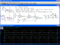
I am trying to come up with a circuit that will allow me to alter the 0-1.0v lambda sensor signal to read from 0-.5v on the low side to 1.0v maximum. This will be used for fuel control in a hydroxy supplemented gasoline powered vehicle. So far I can only get the low end to read .224v with maximum of 1.0v. VR2 and VR4 set max output when a 1.0v signal is applied, and VR1 and VR3 are my low end adjustment. Can anyone help me get the voltage on low end to be adjustable from 0-.5v while still maintaining the 1.0v max output? Building circuits I am good at.....designing is another story entirely. Thanks in advance for any help.:)
 

beenthere

Joined Apr 20, 2004
15,819
That file type won't open on my computer. Can you post it up in .jpg or.bmp or even .pdf format?

Hopefully you are aware that fudging an engine sensor signal can cause bad things to happen to your engine, and that nobody has yet to demonstrate the utility or effectiveness of adding H2-O2 gas to the air inlet of an IC engine.
 

Thread Starter

Capt-Killjoy

Joined Sep 29, 2008
58
Hopefully this schematic will open. As for the effects of hydroxy gas in an ICE.....I have already gained 5 mpg with the addition of hydroxy so far, but need to be able to further modify my fuel trims to reach a fuller potential. And without any adverse effects. Proof of the pie isn't always in the pudding....this time it is in my gas tank! Thanks again for any help.:)
 

Attachments

SgtWookie

Joined Jul 17, 2007
22,230
Well, there are a couple different basic types of O2 sensors. The older types were a yes/no kind of thing; either the presence or absence of oxygen. The output went from nearly 0v to nearly 1v, and there's no in-between.

During closed-loop operation, the ECU constantly monitors the output of the O2 sensor; if there is no oxygen sensed, the computer leans the mixture until oxygen is sensed; then it's too lean, so the computer makes the mixture more rich until no oxygen is sensed. The process repeats continuously while in closed-loop operation. If you try to modify the output of one of these older-type sensors, you'll be running the ECU in open loop mode.

Newer type O2 sensors have a continuously variable output. If you had one of these, it would be pretty easy to add or subtract an offset voltage to get the mix desired.

Of course, if you try to retrofit an older vehicle with one of these newer O2 sensors, it'll never pass a visual emissions inspection.
 

Audioguru

Joined Dec 20, 2007
11,248
Hydroxy fools the ECU into making the mixture too lean. So less fuel is burned and the valves and pistons are burned instead. Nitrogen Oxide pollution becomes very high.
 

Thread Starter

Capt-Killjoy

Joined Sep 29, 2008
58
I guess I didn't make myself clear on what I was asking. First off, I am a Ford Certified Senior Master Technician with 35+ years working on these crates, so I don't really need a lesson in how an O2 sensor works. What I would like, is help with the circuit design so that I can vary my low side voltage in order to have my 02 sensor voltage to never go below whatever I have it set to. (Ideally, would like to adjust from 0v up to .500v) With the circuit as it is now, I can only set the switching from .226v to 1.0v. Can anyone help me with this problem? Thanks in advance.
 

SgtWookie

Joined Jul 17, 2007
22,230
I guess I didn't make myself clear on what I was asking. First off, I am a Ford Certified Senior Master Technician with 35+ years working on these crates, so I don't really need a lesson in how an O2 sensor works. What I would like, is help with the circuit design so that I can vary my low side voltage in order to have my 02 sensor voltage to never go below whatever I have it set to. (Ideally, would like to adjust from 0v up to .500v) With the circuit as it is now, I can only set the switching from .226v to 1.0v. Can anyone help me with this problem? Thanks in advance.
I respect your long experience with maintaining FOMOCO designs.

But from the engineering side of the house, your idea won't work with the old O2 sensors.

You're trying to "trick" the computer into staying in closed-loop mode when the lambda sensor is way out of it's range. Burned/broken pistons, valves, broken head gaskets, and a wide variety of other ills are in your future if you attempt this.

You know how to fix such things for minimal costs. Most other people don't.

It would be irresponsible of me to post a circuit to perform what you seek, because many "HHO" fanatics may attempt to seize upon it as "gospel", and promote it as such. A great many broken motors would result. Good for mechanics, bad for the general population.

There is no "fix" for the old-type O2 sensors. They are what they are. Trying to operate them out of their envelope will result in disaster - for the individual who has to pay their mechanic to fix their badly broken motor.

Burnt pistons, burnt valves/seats, broken rings/lands, hammered rod/main bearings, you name it. Bad juju.

OTOH, the newer type O2 sensors have an output that can be offset.

Maintaining stuff is very different from engineering stuff. We can agree that there is not enough feedback from the maintainers to the engineers. I've been on both sides of that fence.
 
Last edited:

Thread Starter

Capt-Killjoy

Joined Sep 29, 2008
58
Hydroxy fools the ECU into making the mixture too lean. So less fuel is burned and the valves and pistons are burned instead. Nitrogen Oxide pollution becomes very high.
Just to keep things straight, Hydroxy doesn't fool the ECU into thinking anything. The Hydroxy gas causes the ECU to read a leaner mix (via the O2 sensors) which causes just the opposite of what you claim. The ECU senses more oxygen (not less fuel. hence the name OXYGEN sensor). In return the ECU causes ADDITIONAL fuel to be fed into the engine which is counter-productive to saving fuel mileage. Also, another misnomer is that NOx goes high.....again, NOT TRUE! The only way NOx go higher is from running hotter, and just running Hydroxy will not cause that to happen.

Look, I don't want to go off topic here as this is an electronics forum and not a HHO forum. God knows there are enough of them to go around already. I am just looking for a simple circuit to do what I want it to do. This is not a spur-of-the-moment idea. This is something I have been working on steadily for some time now and making some REAL gains without damaging anything. My oxygen sensor signal has been running modified for months without any ill effects. I am just looking for a better way to make it happen and take my research further.

Even though my project may sound risky, (and I do appreciate all of your concerns for my vehicle), I would hope that there is someone out there who won't mind helping me modify my circuit to give me more gain on the low side. Remember, keeping an open mind makes new things happen.

This will be the last post of mine concerning ANY Hydroxy data, I promise.
But please.....will someone give me a hand instead of a lecture? (Didn't mean to sound so crabby but, at age 50, I think I have already had my fair share of lectures...LOL) Thanks again for any help anyone can give.:D
 

SgtWookie

Joined Jul 17, 2007
22,230
Just to keep things straight, Hydroxy doesn't fool the ECU into thinking anything. The Hydroxy gas causes the ECU to read a leaner mix (via the O2 sensors) which causes just the opposite of what you claim.
We are in complete agreement here.
The ECU senses more oxygen (not less fuel. hence the name OXYGEN sensor). In return the ECU causes ADDITIONAL fuel to be fed into the engine which is counter-productive to saving fuel mileage. Also, another misnomer is that NOx goes high.....again, NOT TRUE! The only way NOx go higher is from running hotter, and just running Hydroxy will not cause that to happen.
I don't have scientific evidence on hand to prove nor disprove your claims. However, I tend to believe that the combustion of hydrogen/oxygen within the confines of a cylinder can only help to lower noxious emissions. My beliefs are completely unscientific, and have no basis in fact.
Look, I don't want to go off topic here as this is an electronics forum and not a HHO forum.
Too late ;)

God knows there are enough of them to go around already. [/QUOTE]
Well, there certainly are a number of them.
I am just looking for a simple circuit to do what I want it to do.
I can appreciate that.
This is not a spur-of-the-moment idea. This is something I have been working on steadily for some time now and making some REAL gains without damaging anything. My oxygen sensor signal has been running modified for months without any ill effects. I am just looking for a better way to make it happen and take my research further.
If you try this, you WILL fry things.

Even though my project may sound risky, (and I do appreciate all of your concerns for my vehicle), I would hope that there is someone out there who won't mind helping me modify my circuit to give me more gain on the low side. Remember, keeping an open mind makes new things happen.
Look, you know how to fix things. I'm not about to put a circuit out there that would potentially cost a lot of people a lot of money.
This will be the last post of mine concerning ANY Hydroxy data, I promise.
Why is that? You no longer beleive in it?
But please.....will someone give me a hand instead of a lecture?
I'm not lecturing you. I'm informing you as respectfully as I can, that what you wish to do is not viable, and the results will be disasterous. While you are equipped to handle it, virtually all of our other readers are not.

I will not post a circuit that I do not believe in.
(Didn't mean to sound so crabby but, at age 50, I think I have already had my fair share of lectures...LOL)
I'm not trying to rain on your parade.

I've already told you what you need to do, and you're disrespecting me by not listening.

Get one of the newer O2 sensors. Then we'll talk.

Thanks again for any help anyone can give.:D
I'm giving you the best scoop I know how to give.

Your idea WILL NOT WORK with the old O2 sensors.

I don't know how much more plain I can be. It's not magic, it's not "someone withholding information" - it just plain won't work.

And if you don't believe that - best take your ideas elsewhere.

Now if you want to talk about offsetting output voltages from more modern O2 sensors - let's talk. But from your approach - it's a dead-end street. It won't work.

And you have ZERO chance on influencing my opinion, because it is based in scientific fact.
 

Thread Starter

Capt-Killjoy

Joined Sep 29, 2008
58
My apologies to all. I apparently forgot to mention that this IS a new vehicle and although it does have the narrow-band sensors, the sensor value IS ENTIRELY modifiable. Damage only happens when you push things TOO far! This project is a 2005 Ford Ranger 4X4 w/a 4.0 SOHC engine. I apologize to all and hope that this new information will prompt some aid. OH......and Sgt. Wookie.......with regards to our e-mail....please know that I do not have ANY hard feelings toward you for your attitude toward myself or my project. I respect the fact that you won't knowingly post a damaging circuit! I am sorry if I got off on the wrong foot with you or anyone else. I hope we can all start over.....
 

SgtWookie

Joined Jul 17, 2007
22,230
Hey, I don't have any hard feelings.

It's just that what you want to do will very likely cause severe engine damage.

With all that said, see the attached.

The op amp I used in the model is a good one, but is no longer available in industrial/military temperature ranges. You can't use a typical op amp like an LM324, LM2902, etc. because their outputs won't go low enough.

There are no bypass capacitors shown across the opamp's power pins. There should be an 0.1uF right across them, and a 10uF or larger cap nearby, minimum 25v rating, 35v preferable.

Automotive environments are electrically very noisy. Your ECU is looking for the lambda crossing 450mV rather than an absolute level. If you get the output near 450mV, you will likely be triggering by noise instead of by actual signal from the sensor. If you increase the offset past 450mV, the ECU will likely either lean the mixture so far that the engine either dies, or your "check engine" idiot light will come on.
[eta]
You undoubtedly know this already, but for the benefit of anyone who doesn't:
The narrowband Lambda sensors' high/low voltage level varies with the temperature of the exhaust system; when cold, it may be from 100mV to 900mV, and when warm it may be more like 250mV/750mV. So, attempting to offset the low side will very likely result in fuel starvation/detonation as the temperature rises.

Caveat Emptor.

The real way to approach this is to use a wideband lambda sensor, with a comparator set to the desired fuel/air ratio level. The output of the comparator should be configured to toggle between 100mV and 900mV.
[eta]
Added voltage regulator to supply.
 

Attachments

Last edited:

Thread Starter

Capt-Killjoy

Joined Sep 29, 2008
58
Thank you very much for your aid Sgt. Wookie. I really do appreciate it and again apologize for not being more exacting and descriptive in my first post. As a diagnostic technician I know first hand how frustrating it is to only have 'half the picture'. I have saved the schematic and will start the build as soon as I find the proper components. Most I already have, but the op-amps I will have to research further. I do have one other request though, if you wouldn't mind indulging me. I was just curious as to exactly how the circuit works. I thought I understood the basic functioning of all the individual components (although that knowledge was acquired a long time ago), but I am quite obviously lacking in that department. Why does each individual op-amp need to have it's own supply as opposed to a quad op-amp with single supply? Also, could you explain the functioning of the NPN transistor placed at the output? I don't understand how the transistor won't be applying Vcc to the output when biased by the input to it. Again, thanks for your help.:)
 

SgtWookie

Joined Jul 17, 2007
22,230
... again apologize for not being more exacting and descriptive in my first post.
Most of the battles around here are beating the details out of the inquirers. ;)
As a diagnostic technician I know first hand how frustrating it is to only have 'half the picture'.
Life would be so much easier if we only had all the details...
...Most I already have, but the op-amps I will have to research further.
Previously I'd specified rail-to-rail, but really it only needs to be able to reach the lower rail for input and output. If it can get within 1.5v of Vcc, that'll be fine.
I do have one other request though, if you wouldn't mind indulging me. I was just curious as to exactly how the circuit works.
R1 and R7 act as a voltage divider. R7 could actually be eliminated, but leaving it in makes R1 much less sensitive when adjusting it. Without R7, only the lower 1/3 of R1 would be useable. R1 provides the voltage to be averaged with the input of the lambda sensor. In the simulation, it reads 1.28V. The LT1013A has a very low offset voltage, so the output voltage is negligably higher (about 35uV, or 0.035mV.)

U1A is a unity-gain buffer. It presents a very high input impedance to the voltage supplied by R1, which keeps the voltage at a relatively constant level.

U1B is another unity-gain buffer, used to isolate the output of the lambda sensor from the averaging network.

R2 and R3 are the averaging network. The input to U2A is the average of the voltages output from U1A and U1B.

U2A is a noninverting amplifier. At the input, P-P voltage is about 400mV, from 690mV to 1.09v. The gain = 1+(R5 / R4). At the output, P-P voltage is about 550mV, from 950mV to 1.5V.

U2B is another unity-gain buffer.

Q1 is an emitter follower. It's basically just an easy way to subtract a fixed 0.6v from the signal output of U2B.
I thought I understood the basic functioning of all the individual components (although that knowledge was acquired a long time ago), but I am quite obviously lacking in that department.
We learn stuff, we forget stuff. Then we re-learn. ;) Thank goodness for the Internet; it sure makes it easy to look stuff up.
Why does each individual op-amp need to have it's own supply as opposed to a quad op-amp with single supply?
That's due to the quirks of this particular PSpice implementation. I'd started off with a LT1014A quad opamp, but it was never offerred in an industrial temp range; so switched to LT1013A dual opamps, which were. Besides, dual opamps generally have better specs than quad opamps; this is no exception. Single opamps of the same type generally have better specifications than dual opamps, but you start using up board real estate in a big hurry.
Also, could you explain the functioning of the NPN transistor placed at the output? I don't understand how the transistor won't be applying Vcc to the output when biased by the input to it.
It's a voltage follower. The emitter will stay about 0.6v less than the base due to R6 and the base-emitter voltage drop.

Just for reference, I'm adding another version of the circuit that shows waveforms at most points. The signal out of U2B is not shown, as it would be superimposed over the output of U2A.
 

Attachments

beenthere

Joined Apr 20, 2004
15,819
That is the same supply rail. It's just easier to follow the schematic if drawn like that. All the Vcc's and ground symbols are attached to the same piece of wire (well, two separate pieces).

The 2N2222 is running in a mode that makes the signal on that 1K resistor go from the source down to close to ground. You would want to make adjustments with the circuit driven by the O2 sensor, but not feeding the ECU until the adjustment for the offset and range are complete.

ECU's with those old O2 sensors tend to run in BANG-BANG mode, with the mix going too rich to too lean. Pulses to the injectors hunt from (relatively) wide to short, but almost never the same.

Unless your H2O2 mix can be varied with engine demand, it may be hard to find anything but a small sweet spot for the addition.

That mix should be neutral to the engine. It is already a perfect mix of fuel/oxidizer, so it shouldn't throw the air/gasoline very far off. You may see a bit more power for a given throttle body setting. Combustion products are mostly more water vapor, but higher cylinder temps will (obviously) cause NOx emissions to rise.

It would be incredibly great if anybody would actually instrument things so a body of valid and repeatable (remember the scientific method?) could grow and be examined.

I have come across rather fanciful instructions to retard the spark considerably when adding H2O2 to the engine. All the way to 180 deg. (the implosion after the explosion is supposed to suck the piston up. Hello to Mr. Newcomen, and impressive with the valves open). Can you add any thoughts to that caution? The H2O2 is supposed to explode with such violence that the pistons will be destroyed with any spark advance.
 
Last edited:

Ron H

Joined Apr 14, 2005
7,063
Capt-killjoy, SgtWookie has provided you with a circuit which will alow you to adjust the gain and offset to maintain the desired range. If you actually want to maintain the same gain, but to simply limit the low end of the range to an adjustable value between 0 and 0.5V, then you need a different circuit.
 

Thread Starter

Capt-Killjoy

Joined Sep 29, 2008
58
I thank you for your help and explanation of the circuit you provided. One other question that comes to mind.....could the NPN transistor be replaced by an LED to provide the necessary voltage drop, much like as I had it in my original circuit? (Still trying to pull old info from the back side of my brain. LOL) I see that BeenThere and Ron H are also contributing and I'm not really sure how this quick reply post set-up works, so I will address both posts in this one. First to BeenThere. I don't mind keeping anyone 'in-the-loop' with solid comparative data that I have gathered during my project, but I promised not to go off topic from electronics. If noone else minds, then I don't mind, but I feel it would be best to do it in personal messages rather than 'muddy the waters' anymore than I feel I already have here. If you would like to pick my brain concerning my data, then feel free to message me.
And now for Ron H's post. If you have a different circuit for comparison I am always willing to try it. I have built so many different circuits as of late, that I am actually starting to enjoy it again. One can never have too many options to choose from. And your description of final results is what I am looking for. The simpler the better, and thank you! The main criteria are: high side can't go above 1.0 v to ECU and low side adjustabililty preferably from 0-.5 v as stated in original post. Thanks again EVERYONE, for your past and continud help.
 
Last edited:

Audioguru

Joined Dec 20, 2007
11,248
Have you driven behind a Ford truck? It stinks! Hardly any pollution controls like cars have.
Your Explorer truck still might meet the relaxed (for trucks) pollution limits after you modify it so that it burns its motor instead of gasoline.

Which costs more. The motor or gasoline?
 

SgtWookie

Joined Jul 17, 2007
22,230
One other question that comes to mind.....could the NPN transistor be replaced by an LED to provide the necessary voltage drop, much like as I had it in my original circuit?
I don't know of any LEDs that have that low of a Vf (forward voltage).

Did you want some kind of constant indication that there was output from the circuit? Another transistor driver could be added from the output of U2B; this time using a 1k resistor to the base, emitter grounded, the LED's cathode on the collector, and a suitable current limiting resistor from the LED's anode to Vcc.
Rlimit >= (Vcc - VfLED) / DesiredLEDcurrent

I think what you really should want to know is if the signal is traversing high enough/low enough so that the ECU is getting what it considers a valid input. You'll eventually find that out when the "check engine" light comes on, or the engine stops running ... but you'll really want to know before that.

I don't know for certain how your ECU will handle not getting the transition, but I believe it'll go to a "default" fuel/advance/etc map.

Just a guess, but I'm thinking that the ECU uses a comparator with a fairly small amount of hysteresis to sense when the lambda has transitioned. No clue what the tolerance might be.

I see that BeenThere and Ron H are also contributing and I'm not really sure how this quick reply post set-up works,...
It's completely asynchronous; sometimes posts are made moments or months apart
I don't mind keeping anyone 'in-the-loop' with solid comparative data that I have gathered during my project, but I promised not to go off topic from electronics. If noone else minds, then I don't mind, but I feel it would be best to do it in personal messages rather than 'muddy the waters' anymore than I feel I already have here. If you would like to pick my brain concerning my data, then feel free to message me.
We would all like to see some real scientific results, objectively reported.
What the test conditions were, what equipment was used; very detailed.

The problem we're all seeing is that there is lots of hoopla and hogwash, with wild claims of increased fuel economy, but no evidence to back it up. There are a lot of wild-eyed innocents willing to plunk down a good chunk of change with the hopes of reducing their expenditures at the gas pumps.

Having someone like yourself who's been a master mechanic for years looking into this could get quite interesting.

But, back to your project. Yes, a wideband lambda sensor will set you back a hundred or so, and you'd need to weld in a fitting to hold the thing. But, you'd actually be able to control your air/fuel ratio accurately over a wide range. Much less risky project than what you're attempting here, as you'll be out of the linear response range of the lambda sensor, and there is no compensation for the actual temperature of the sensor itself - which will vary it's output voltage by perhaps 150mV.
 

Thread Starter

Capt-Killjoy

Joined Sep 29, 2008
58
So does this mean that the circuit you provided attenuates the output signal from the high side as well as the low side? (i.e. compressing the entire switching waveform?) The ideal action for the output is to have a full swing each cycle to as close to 1v as the O2 will drive the voltage, with no reduction of voltage except to keep it at or below 1v. The only addition of mV would be to the low side of the switch cycle. In order to keep the CEL off, the duty cycle of the output signal still needs to be maintained as dictated by the actual O2 sensor signal input. A slight delay in signal reception isn't an issue, but maintaining as full of a swing as possible does matter. A compressed signal (i.e. not able to go full rich at 1.0v) will set the CEL everytime after the second drive cycle the vehicle makes. Sorry if I again withheld any information. I know what I want, but putting the exact description down into words seems most difficult for some reason. And as for the wideband sensor idea...it is definatly the way to go, as most of the newest vehicles are now starting to come with the wideband sensors, and soon will all be so equipped from the skinny I have heard. But I am trying to maintain the basic control system of the actual vehicle with only modified sensor values for this part of my project. The only non-stock engine component I have added is EGT sensors in both banks of the engine to closely monitor my exhaust gas temperature so that in the event of a problem I will know, hopefully well in advance, of pending engine trouble and can shut everything down with the flick of a switch. Thankfully, I have yet to have to actually use that feature. Eventually I am looking for a circuit that will allow all 6 injector pulse-width signals to be modified as well, but getting a stable, properly working lambda signal modifier is tops on my hit parade for now.

Oh, and AudioGuru...you are correct about the relaxed emmission standards for trucks and SUV's here in the US. I never could figure that one out! You can't tell me that the automakers couldn't design an engine to run as efficiently in a truck as they can a car. In several cases it is the SAME engine only mounted horizontally instead of transverse, and the power-to-weight ratio can't be that much different. IMHO, that is. Maybe I'm wrong, but that information is relatively useless to me at this point so I don't lose any sleep over it. Take care and thanks for your input.
 
Last edited:

SgtWookie

Joined Jul 17, 2007
22,230
So does this mean that the circuit you provided attenuates the output signal from the high side as well as the low side? (i.e. compressing the entire switching waveform?)
When the fixed offset voltage is averaged with the lambda signal, the amplitude of the lambda signal is reduced.

However, it is then amplified (U2A, R5,R4) so that the net result will be the high output will be the same as it was on input (0.9v in = 0.9v out) but the low side will be offset higher (0.1v in = 0.1v to 0.5 out, adjustable). The overall amplitude of the signal has to be reduced to keep the output <1v.

The ideal action for the output is to have a full swing each cycle to as close to 1v as the O2 will drive the voltage, with no reduction of voltage except to keep it at or below 1v.
Provisions for those adjustments are via R1 (offset) and R5 (peak amplitude)

The only addition of mV would be to the low side of the switch cycle.
That's basically what the circuit does.
In order to keep the CEL off, the duty cycle of the output signal still needs to be maintained as dictated by the actual O2 sensor signal input.
Therein lies the rub. As the EGT increases, the P-P amplitude of the lambda sensor will likely decrease, from an initial 0.8v (0.1v-0.9v) at normal operating temperature to perhaps 0.5v (250mV-750mV) at high EGT. I don't have exact numbers for you, but you could certainly find out if you have the right equipment - and I'm reasonably certain that you do ;)

The concern is that if you attempt to offset the low side of the signal too much when EGT is normal, at higher EGTs the reduced signal input from the lambda sensor will cause the output of the offset amplifier circuit to not cross the ECU's trigger threshold.

For example, let's say the ECUs' trigger threshold is 450mV (which is what I've been reading). The ECUs' input senses when the lambda input crosses that threshold, going towards too rich or too lean. If you start off with a lambda sensor that normally outputs 0.1v to 0.9v, then add an 0.3v offset to the bottom side along with limiting the high side, you now have a 0.4v to 0.9v signal. But if your EGT goes high (like, you're pulling a heavy load, etc.) the lambda signal starts decreasing - let's just say 0.2v to 0.8v, or 0.6v p-p.

The offset amplifier circuit is still adding the 0.3v offset, so now your output is 0.5v to about 0.78v. Oops, the low side doesn't go low enough to trip the ECU's comparator anymore, so the system either goes into open-loop mode and trips the CEL, or leans the mixture so far that your EGT skyrockets along with detonation occurring in the cylinders.

A slight delay in signal reception isn't an issue,
A narrowband lambda sensor's output is maybe 3-4 cycles/second on a good day with a tailwind. Even a 40-year-old design opamp will keep up with that easily. [eta] However, the old designs won't input/output down to the negative rail (in this case, 0v since it's a single supply) and they have relatively poor stability as far as input offset voltage is concerned.
but maintaining as full of a swing as possible does matter. A compressed signal (i.e. not able to go full rich at 1.0v) will set the CEL everytime after the second drive cycle the vehicle makes.
Well, within limitations. As long as the ECU is receiving transitions across that 450mV point at least every second, perhaps two, it'll not worry and be happy.

Sorry if I again withheld any information. I know what I want, but putting the exact description down into words seems most difficult for some reason.
That is indeed the biggest battle we fight around here - getting a thorough description of the scenario. ;)

And as for the wideband sensor idea...it is definatly the way to go, as most of the newest vehicles are now starting to come with the wideband sensors, and soon will all be so equipped from the skinny I have heard.
And in your application, it's really the only way to go. You're attempting to utilize a narrowband sensor outside of it's linear region. It may actually work somewhat OK in a narrow band of EGTs, but without active compensation for lambda variation over the complete EGT range, you're begging for disaster. This is why I was so reluctant to do anything about it in the beginning.

But I am trying to maintain the basic control system of the actual vehicle with only modified sensor values for this part of my project.
You'll really need to get more involved than that. Adding wideband lambda sensors will be a heck of a lot cheaper than replacing the engine.

The only non-stock engine component I have added is EGT sensors in both banks of the engine to closely monitor my exhaust gas temperature so that in the event of a problem I will know, hopefully well in advance, of pending engine trouble and can shut everything down with the flick of a switch.
That was a very good idea. You have probably noticed a decrease of EGTs when your system is in use; but that's a guess on my part. I would like to know what "system on" and "system off" readings are under similar driving conditions (ie, cruise, light accelleration, heavy load, etc)

Thankfully, I have yet to have to actually use that feature.
I'll bet you'll need it when you start using the offset circuit.
Eventually I am looking for a circuit that will allow all 6 injector pulse-width signals to be modified as well, but getting a stable, properly working lambda signal modifier is tops on my hit parade for now.
You can modify the injector PW by changing ECU inputs, but you'll still be dealing with the production map for open-loop operation.
 
Last edited:
Top