Dual brightness LED from D-Type Flip Flop

Thread Starter

Jakeeh9

Joined Nov 28, 2019
12
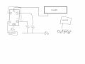
I have a D-Type flip flop circuit set up to flash a pair of LEDs on and off in turn. One LED is connected to Q and the other connected to NOT Q. The data pin is also connected to NOT Q. This means that every time there is a clock pulse, the LEDs swap state, so one is on and the other is off.

I want to be able to make the same 2 LEDs flash at a different brightness when an LDR circuit outputs a logic 1. The LER is connected to a Schmitt Inverted so that I get a digital output.

When the light level falls below a certain level (Schmitt will output logic 1), I want the LEDs to flash but at a lower brightness.

Incase it makes a difference to the circuit design, I will be using a PICAXE microcontroller to control when the flashing sequence is active. I was also assuming that the Schmitt output would go into the microcontroller, on which case it would be easier to assume that the flip flop is given power from the microcontroller, i.e the flip flop is only on when the microcontroller output is at logic one

Hopefully that description wasn't too confusing, and any help that I could get would be very much appreciated.
 

AlbertHall

Joined Jun 4, 2014
12,344
The PICAXE could do all of it - no need for the flip flop and it could use PWM to control the brightness - so no extra hardware needed.
 

Thread Starter

Jakeeh9

Joined Nov 28, 2019
12
You can do this with an analog switch. The LED is connected to the common point and the switch selects either one of two resistors to power the LED at the desired brightness levels. LED brightness is controlled by current.

https://www.onsemi.com/pub/Collateral/NLX2G66-D.PDF
Thanks, but it's going to be an automated system, so a switch would be no good, as you have to physically switch it
 

Thread Starter

Jakeeh9

Joined Nov 28, 2019
12
Ahh, I hadn't realised that because we had been using an exam board specific simulation that did not include it, however for this project I can use it.

I have heard of PWM before, however, I am unfamiliar with it, and don't know how to use it.

I know that the Period is simply the length of one cycle, but I don't know how to calculate the period that I should be using.

I also know that the duty cycle is the percentage of the cycle that the output is high. Having done some research, I have found that the higher the duty cycle the brighter the LED, which makes sense to me.

If I want to have an LED that runs at 70% brightness until I tell it otherwise (several seconds later), what values would I need for Duty cycle and Period. The duty cycle is as a percentage of 1023 for the picaxe, so I think I would be needing just over 700, but I'm not too sure. As for the duty cycle value, I have no idea :p
 

AlbertHall

Joined Jun 4, 2014
12,344
Yeah, you've got the duty cycle sorted. For dimming LEDs the period is pretty irrelevant providing it isn't really, really long in which case the LEDs would flash for each pulse of PWM. Anything less than 10ms (faster than 100Hz) will do the job.
 

Thread Starter

Jakeeh9

Joined Nov 28, 2019
12
Yeah, you've got the duty cycle sorted. For dimming LEDs the period is pretty irrelevant providing it isn't really, really long in which case the LEDs would flash for each pulse of PWM. Anything less than 10ms (faster than 100Hz) will do the job.
Alrighty, I will give that a go tomorrow :)

Also, due to the logarithmic response of the eye, 70% brightness will barely look any different than 100%.

Bob
Thanks, I'll make sure to use a bit less than 70 then. I've not worked out how bright I want it yet, was just giving that as an example
 

Thread Starter

Jakeeh9

Joined Nov 28, 2019
12
Welcome to AAC!
Can you post a schematic of your setup?
Here's a crudely drawn diagram of what I want (I know I forgot resistors with the LEDs). The flip flop gets its power from the picaxe because I only want it to flash some of the time, so I'm assuming this would work

Basically when the output from the logic circuit is high, I want the LEDs to continue flashing as they are, but at a lower brightness
 

Attachments

danadak

Joined Mar 10, 2018
4,057
You can do this with ATTINY85 using mBlock to program it.

mBlock takes the blocks you drag and drop and interprets them into Arduino code
for you.

This example should work, can be simplified if you use a subroutine for setting PWMs,
I just got lazy.

1574982569238.png

If you use Arduino Nano board this programs the board. If you use ATTINY85 chip
you use a Nano or Uno board to do the actual ATTINY85 part programming.


Here is the code produced for you by mBlock -

1574982767729.png


Regards, Dana.
 

Papabravo

Joined Feb 24, 2006
21,158
Thanks, but it's going to be an automated system, so a switch would be no good, as you have to physically switch it
No! No! No! An ANALOG SWITCH is an IC that can be switched by another circuit. It is not a mechanical switch requiting manual operation. Look at the damn datasheet before shooting off your trap.
 

Thread Starter

Jakeeh9

Joined Nov 28, 2019
12
You can do this with ATTINY85 using mBlock to program it.

mBlock takes the blocks you drag and drop and interprets them into Arduino code
for you.

This example should work, can be simplified if you use a subroutine for setting PWMs,
I just got lazy.

View attachment 193365

If you use Arduino Nano board this programs the board. If you use ATTINY85 chip
you use a Nano or Uno board to do the actual ATTINY85 part programming.


Here is the code produced for you by mBlock -

View attachment 193367


Regards, Dana.
Thanks for the response, but I HAVE to use a picaxe microcontroller. It is for an A-Level project and the exam board will only allow us to use them, even though arduinos are better in almost every way!
 
Top