Dual Active Bridge Converter for Project. PLEASE HELP

Thread Starter

TheticVoyage630

Joined Sep 15, 2024
25
Hello everyone,

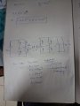
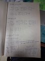
I'm currently working on a simulation for a dual active bridge (DAB) converter and could really use some help. I've designed the converter and derived both the large signal and small signal models. I've also worked out the equations for power and the average current through the leakage inductance, which I've attached to this post.

My current setup includes a resistor as the load, but I want to add a battery for CC (constant current) and CV (constant voltage) charging, along with bidirectional charging capabilities. I'm struggling with a few points:

  1. Closed Loop Control: How do I incorporate closed loop control in this system? I'm looking for guidance on the design and implementation of the control loop.
  2. Bidirectional Charging: I want to achieve bidirectional charging without changing the output voltage or current. How can this be done effectively?
  3. Developing the Closed Loop Converter: Any advice or resources on developing the closed loop converter for this circuit would be greatly appreciated.
I’ve attached my derived equations and models for reference. Your insights and suggestions would be incredibly helpful. Thank you!

Please tell me if I am getting something wrong here..how do i change the D value withut altering the voltage and current..please help me i am so confused :(
 

Attachments

Ian0

Joined Aug 7, 2020
13,097
Bidirectional Charging: I want to achieve bidirectional charging without changing the output voltage or current. How can this be done effectively?
It can't. If you charge at a constant current, then the battery voltage rises. If you charge at a constant voltage, the current falls.
 

Thread Starter

TheticVoyage630

Joined Sep 15, 2024
25
It can't. If you charge at a constant current, then the battery voltage rises. If you charge at a constant voltage, the current falls.
Hi Ian,

Thank you so much for responding to my previous question. I really appreciate your help!

I have a few more doubts regarding power converters and their design. When designing a power converter, what details do we typically need to know? I understand that we need to know the power required at the output, but what other details are usually provided? Are the load values and output voltage given? What are the usual design specifications?

Additionally, I have a question about battery charging. Why is it that at constant current, the battery voltage rises, while at constant voltage, the current drops? Is this done to maintain a constant output power? Is that how compensation works?

Thanks again for your assistance!
 

Ian0

Joined Aug 7, 2020
13,097
The output load is the most basic of the specifications. If you know power and voltage you can work out current etc.
There may also be specifications for the minimum load, the efficiency, the isolation voltage, the accuracy of the output voltage, the maximum amount of ripple.

In most battery chemistries, the open-circuit voltage varies with the state of charge. Lead Acid is perhaps the easiest to understand in this respect, as the acid strength increases as it is charged and decreases as it is discharged, and the open-circuit voltage is proportional to the acid strength, varying from 11V to 13V for a 6-cell battery. The battery also has internal resistance, so the voltage you measure will be Voc+IR as it is charging and Voc-IR as it is discharging, where I is the internal resistance.

It is therefore obvious why the terminal voltage rises during a constant current charge.
For a constant voltage charge, Voc is still increasing as it charges, but the terminal voltage (Vt) is kept the same.
Vt=Voc+IR ,so I must reduce.
Each type of battery has its own charging regime specified by the manufacturer.
 

Ian0

Joined Aug 7, 2020
13,097
Unfortunately, no. :( I did work on a project involving the LLC resonant converter circuit, but my teammate primarily focused on that section of the converter...
Perhaps either of them would be a better place to start, before incurring the extra complexity of the dual active bridge.
You would have to forgo the bidirectional charging for now.
 

Thread Starter

TheticVoyage630

Joined Sep 15, 2024
25
Btw i just had a doubt regarding the small signal analysis and steady state model of the converters..what are the purposes of each? is the small signal model responsible for controlling the transients of the converter and steady state model the steady state operation? and if i were to implement a controller..which model (small signal or steady state) would i use and how would i design the controller to help stabilize my system? As per my understanding sometimes to control the steady state operation we use feedfwd compensation..could you please help me here..
 

Thread Starter

TheticVoyage630

Joined Sep 15, 2024
25
Perhaps either of them would be a better place to start, before incurring the extra complexity of the dual active bridge.
You would have to forgo the bidirectional charging for now.
Btw i just had a doubt regarding the small signal analysis and steady state model of the converters..what are the purposes of each? is the small signal model responsible for controlling the transients of the converter and steady state model the steady state operation? and if i were to implement a controller..which model (small signal or steady state) would i use and how would i design the controller to help stabilize my system? As per my understanding sometimes to control the steady state operation we use feedfwd compensation..could you please help me here..
 
Top