DS90LV032A connection Questions

Thread Starter

brettsrt

Joined May 9, 2019
50
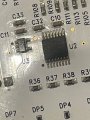
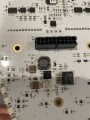
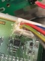
Hi i have a two different boards that connect via 10 different pins that i do not know which pins to connect to each location. Both boards have the same chip that most of the pins go to which is a DS90LV032A any help or thoughts would be appreciated see attached diagram
 

Attachments

MisterBill2

Joined Jan 23, 2018
27,508
Does the TS even know for certainty that the two boards connect??
And it seems that there must be a lot of other circuitry on each of those boards. What I see is that the two boards do not connect directly, but rather both connect to another item that we do not see. This is verified because one board has a Vcc connection and the other one does not have any Vcc connection.

So what we see is two pieces of the puzzle that do not go together.
 

Thread Starter

brettsrt

Joined May 9, 2019
50
Does the TS even know for certainty that the two boards connect??
And it seems that there must be a lot of other circuitry on each of those boards. What I see is that the two boards do not connect directly, but rather both connect to another item that we do not see. This is verified because one board has a Vcc connection and the other one does not have any Vcc connection.

So what we see is two pieces of the puzzle that do not go together.

yes there is other things going on but those connections are are there this is the only connection that is unknown from the whole system
 

MisterBill2

Joined Jan 23, 2018
27,508
Given the disparity of the function identifications and the difference in the number of SIGNAL types, it looks to me like the two connectors both connected to a missing piece. The one set of conductors matches the color code of a cat5 data cable, sort of. Are the connectors ribbon cable types, or some other kind?
 

Thread Starter

brettsrt

Joined May 9, 2019
50
There was a mistake made the diagram was wrong:

J6 is the Master Board - connects Ultimately to J1....

Photo of layout update - for whatever reason this isnt talking as it should.... maybe something isnt connected correclty...layout update.jpg

Master PCB Board: contains a DS90LV047A 3-V LVDS Quad CMOS Differential Line Driver (8 Pins, 4 Ports, showing 2.47V on all solid negative side of ports, and 4.6mV to 3.3mV on all positive side of ports)
& also on the same connector a SN65LVDS2DBV (SN65LVDxx Single High-Speed Differential Line Receiver) **which oddly shows 3.2V on both input pins** 2 pins

Connected Board:
contains a DS90LV048A 3-V LVDS Quad CMOS Differential Line Receiver (8 Pins, 4 Ports) connects to masters 8 pins 4 ports per datasheet port 1 to port 1 positive to positive negative to negative & also on the same connector a DS90LV011A 3V LVDS Single High Speed Differential Driver - 2 pins
 

Attachments

MisterBill2

Joined Jan 23, 2018
27,508
The pictures of the ICs tell me nothing except what they look like. I see connections from an IC to a multi-pin connector Are both J1 and J6 ribbon cable connectors?? I see a small portion of connector J6, seeing all of it would be much better than just part of it. AND what is on the other end of those wires????Is it a connector??? or are they simply cut off?? In the drawing they go to an IC and clearly that is not the case.
Why are you not showing the connectors on the circuit boards?? The information needed has been hidden while the information I do not need is presented very well.

And since it appears that the TS has already decided what must connect, why are you asking us??
Probably some other connection is also involved, AS IS OFTEN THE CASE. So show us more of the assembled system and we may be able to suggest an alternative scheme that will work. Consider that what is done already may not be the only reasonable scheme. And given that it does not work, some other part must also not be as it should be. probably the J1 connector does not match whatever is on the other end of the wires from J6, and the reason is because that is not where it should be connected.
 

MisterBill2

Joined Jan 23, 2018
27,508
It does help some. Looking at the various pictures and seeing several open connectors, along with seeing another larger PCB that is not among what we are shown, it is clear that this is quite a large system. and I see that the one jumper assembly has a 14 position connector on one end, which does not match either of the connectors we see. while the connector on the other end is a 12 position connector. This leads me to conclude that, if all of the pieces are shown, that there are at least two open connectors and at least one missing jumper connection assembly. So this appears to be a puzzle with a few missing pieces.
 
Top