Dropping from kws to 12 volts

Thread Starter

Zahidr

Joined Sep 24, 2018
26
Hi,

I understand in a simple circuit examples you have
battery 9v ,
2v LED @ assumed current 20mA ,
resistor of 350 ohms.
( 9-2)/.02.
So with the right size of resistor only allows 2v to be sent to LED.

In the pictures attached below.

I want to understand what components are needed and what they do in the situation when power source is a 130 kw three phase generator when the consumer components are 20 kw motor and start /stop button . So that just enough needed voltage is sent to the 20 kw motor and 12v -24v button just like like 2v LED.

I think the wires from Generator carry 210 volts or 415 volts in total.

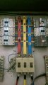
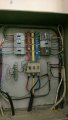
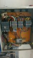
I have attached pictures of the main distribution box which shows reduced wire gauges coming from component going to panels.
Comparatively the wires coming from Generator are bigger in size (60 mm I think).

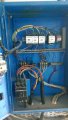
Then the control panels showing varied size of wires with switches and components. The thinner wire go to on/off switches and bigger wired go to 20 kw go to motor.
 

Attachments

Audioguru

Joined Dec 20, 2007
11,248
You and your photos do not say the voltage and how many phases the motor needs.
If the motor voltages are the same as the generator voltages then simply calculate the current then select wires and a switch rated for that current.
 

Thread Starter

Zahidr

Joined Sep 24, 2018
26
The motor are 3 phase motors , 30 HP or 22 kw.

Voltage coming from Generator is
210 volts also three phase Generator.

The distribution box says danger 415 volts.
 

Thread Starter

Zahidr

Joined Sep 24, 2018
26
Starting with distribution Box.
I have attached three images of distribution box.
As you can three 60 mm wires coming up the box from the Generator. Then there are smaller wires going to control panel.
What is the component where the smaller wires coming from. What is the component doing ?
 

Attachments

WBahn

Joined Mar 31, 2012
30,088
I would strongly recommend that you not try to mess around with this yourself -- get a qualified electrician to do the work and have them explain things to you as they go and answer your questions. That way you learn something and the work gets down safely and correctly. But if you try to do this yourself there is a fair chance that you are going to get tangled up with a 3-phase power system capable of lighting you up in a heartbeat (very possibly your last heartbeat).
 

Thread Starter

Zahidr

Joined Sep 24, 2018
26
Don't worry I am not doing the work. The system is in place and working. I just want to know what components are used or how does dropping the power works in the pictures.
 

ebp

Joined Feb 8, 2018
2,332
If there are things that operate on 12 volts, there will be a transformer to step down the voltage. The grey thing with the red and white label on the right hand side of the second photo in your first post may be a transformer, but I can't tell for sure. Using resistors to drop voltage is not practical for this sort of thing because a great deal of power would be wasted as heat in the resistors. Additionally, a transformer makes the low voltage circuit safe because nothing in that circuit has any direct connection to the dangerous high voltage - the transformer "isolates" the two sides.

A light emitting diode can be thought of as a current operated device. The voltage across it is more or less constant with varying current.The voltage does increase with increasing current, but not linearly like it does in a resistor. You can't connect an LED directly to a constant voltage power supply. If the LED forward voltage is less than the power supply voltage it won't light up If the LED forward voltage is less than the power supply voltage, then the current will be very unpredictable. With just the right supply voltage the LED might light and get a safe level of current, but if the supply voltage is just a little higher the LED might be forced to operate at a current that is very much higher than it should be and be destroyed almost instantly. Try your calculation a little differently. Change the supply voltage by a volt or two and calculate the current through the LED for the same resistor value. They try changing the LED voltage by half a volt and see how the current changes. Finally, change your supply voltage from 9 volts to 3 volts and do some calculations with small changes in the supply voltage and the LED voltage. A spreadsheet makes this easy.

AC motors are designed to operate with a constant voltage supply and the current through them depends mostly on how much load there is on the motor. A motor won't be damage if the supply voltage is a bit higher or lower than what the motor is designed for. In the systems you are looking at, the generator must be producing the correct voltage for the motors. In a 3-phase "Y" system the voltage between two phases differs from the voltage from a single phase to "neutral." For example, if the voltage from a single phase to neutral is 120 VAC, the voltage between two phases will be 208 VAC. You can find all of this explained in detail on the web.
 

Thread Starter

Zahidr

Joined Sep 24, 2018
26
The three light coloured devices on the left hand side in
IMG-20180930-WA0057.jpg which is used to step down voltage.
Are they called transformers ?
It has black on off button on top.

I know all six components do the same thing which is to step down voltage /current . the three light coloured on the left and the Two grey with one light coloured.

for example the bottom light coloured device on the left has three wires brown, yellow, blue which I know go directly to the 22 kw motor control panel which switches the motor on and off.

I can read more about the device if I knew the name of device.
 

Attachments

ebp

Joined Feb 8, 2018
2,332
I think those things are circuit breakers - overcurrent protection devices. If they are, they are probably "magnetic" types - the current to the load goes through the windings of an electormagnet. The force an electromagnet produces is proportional to the current, for a fixed number of turns. If the current gets to high the force is sufficient to cause the contacts to open, just as if you operated it manually like a switch.

Circuit breakers often incorporate some sort of delay mechanism so that they will allow higher current for a short time. In magnetic circuit breakers this can be done by using a moving magnetic (iron alloy) core in a viscous fluid. If the force on the core lasts long enough it moves to where it allow the magnet to produce greater force to open the switch. If the force doesn't last, the a weak spring returns the core to the "resting position." Again, you should be able to find lots of info on the web.

There is no chance that those devices are anything that changes voltage. They are much much too small to do that for 22 kW loads. A transformer for that amount of power would probably weigh over 100 kg.

AAC member MaxHeadRoom knows all about this stuff. Perhaps he will drop by. Even with the out-of-focus pictures he might be able to identify the devices.
 

Thread Starter

Zahidr

Joined Sep 24, 2018
26
CIRCUIT BREAKERS. So those devices are circuit breakers which protects against over current. The fact it has 60 mm wires as input (from GENERATOR) and 25 mm wires output going to control panel was just there to confuse me to let me think there was voltage drop taking place.
Circuit Breakers have nothing to do with dropping voltage or current.

In the event there is over current the button will automatically go to off position and open the circuit. Then it can be turned on again later to close the circuit.

As good practice circuit breaker is the first device which should be employed from incoming voltage /current .

Do I understand it correctly ?
 

geekoftheweek

Joined Oct 6, 2013
1,223
From what I remember from my limited experience...

IMG-20180930-WA0057 --> All circuit breakers (not positive on the main feed... maybe fuses)
IMG-20180930-WA0058 --> Circuit breaker bottom left. The white boxes look to be relays. I'm agreeing with ebp with the grey gizmo right of the relays is probably a transformer. From my experience industrial controls normally use 24 volts, but yours may be different since you're asking about 12 volts..
IMG-20180930-WA0060 --> Top row -- Circuit breaker on left then the small white deal I would guess is a fuse holder followed by three relays. The small brown looking wires on the left sides would be your control signals. The last one I'm going to guess is used as a brake for a motor by the way the wires on top are connecting the three phases together. Either the middle one or the last one should be on, but not both at the same time. The left one probably runs a different motor. The white box with adjustments under the first relay may be a relay with over current protection built in so it opens if there is an over current situation and needs to be reset manually... or a time delay relay (the dials should point you in the right direction) The bottom two look like basic terminal blocks from what I can remember, but not sure why they would have used them instead of going straight to the breaker or relay. The deal with the red wire looped around it in the top left is some form of current sensing device that detects how much current is flowing through the wire. It may go to an ammeter somewhere on the door I would assume.
IMG-20180930-WA0062 --> A hand full of relays of various types. The one with the red button is for sure an over current type that will open on an over current situation. The button is your reset. The rest look like normal on and off types. It's hard to make out the bottom right, but it's possible it is a socket for yet another relay.

Chances are your motor is designed to run at the voltage the generator puts out or something close enough to it. All that information should be on the plate on the motor. Anything less would need an external transformer and as mentioned before it would take a decent sized transformer... like at least a compact refrigerator size or better.

The motor will only draw what power it needs to run at the specified voltage unlike an led which needs a resistor to keep it from drawing too much... kind of had the feeling you may have been thinking this way.
 
Last edited:

Thread Starter

Zahidr

Joined Sep 24, 2018
26
Does the diagram in attachment Screenshot_20181001-211653.png show a full proper safe circuit wiring with all components needed to wire a 3 phase power source to a 3 phase motor for industrial purposes.
 

Attachments

Thread Starter

Zahidr

Joined Sep 24, 2018
26
Thank you everybody. Along with your emails and good relevant YouTube I have managed to getting an understanding of over current protection. The use of contactor and their ability have both high voltage and low voltage current.
low voltage for buttons and high low for L1,L2,L3 to T1,T2,T3.
Mutually exclusive contactors for forward and reverse.
Having to use three contactors for star -delta with timer , along with current protection and mcb.

Regards

Zahid
 

geekoftheweek

Joined Oct 6, 2013
1,223
Does the diagram in attachment Screenshot_20181001-211653.png show a full proper safe circuit wiring with all components needed to wire a 3 phase power source to a 3 phase motor for industrial purposes.
Probably would work, but my knowledge is limited... I do know that any switches for guard doors, or other safety devices have to be able to open all contactors at the same time so your emergency stop circuit would go between the SP circuit breaker and the contactor (or contactors). With a single motor it's a lot less work involved.
 

Thread Starter

Zahidr

Joined Sep 24, 2018
26
Thank you.
I was trying to understand the wirings in the initial pictures.
For example in the image IMG-20180930-WA0061.jpg , I can see that is a star delta configuration with the three contactors and a small timer.
When that machine is started it starts slowly and as per timer then kicks off
 

Attachments

Thread Starter

Zahidr

Joined Sep 24, 2018
26
The most "shocking " fact I came across see image attached (Screenshot_20181002-105023.png ) was showing how to light a 2v led from mains 240 volts, using only a breadboard resister and the thickness of the wire in the resistor limits the current and voltage .
No wonder Chinese electronics are so cheap !
Now I can replace my 9 v battery and make direct contact with my breadboard to Mains easily and cheaply and practice my 'helloworld' circuits.
 

Attachments

Top