Driving a Constant Current Through a Resistive Load Without Either Side of Load Having a Fixed Voltage (Floating Load)

Thread Starter

jannerfish

Joined Jan 21, 2016
22
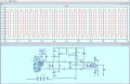
All the constant current circuits I've seen (example below) have one side of the load at a fixed voltage.

const_I.png

However, I want both side of the load to be free to change voltage. My general idea for doing this is attached but I don't know how to bias the BJT gates to achieve the same precise 10mA through each BJT. Presumably the biasing of each gate needs to be related to the other somehow.

General idea is that the gates are biased to achieve 10 mA emitter current in NPN and PNP BJT.
Each gate then remains at a fixed voltage.
Vce of both BJTs are then free to change as resistance of gauge changes - therefore voltage on either side of gauge is free to change.

Is this a good approach for what I'm trying to achieve or is the a better alternative?

StrainGauge.png

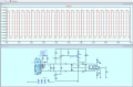
I've attached the LTspice of the above, but it isn't a working model yet (SpringyLoad.asc)
 

Attachments

Last edited:

crutschow

Joined Mar 14, 2008
38,320
I see no reason to have the strain gauge floating as you show, since the output is AC coupled.
What can't one side of it go to ground or a fixed voltage?
 

MisterBill2

Joined Jan 23, 2018
27,181
My question is that if both sides of the load are affected by some external voltage other than that which is holding the current constant, then you have a control problem. Certainly a constant current source can be floating so that both ends of the load can float. So really it becomes an issue of the CC control scheme having an adequate compliance voltage range.
 

Thread Starter

jannerfish

Joined Jan 21, 2016
22
I see no reason to have the strain gauge floating as you show, since the output is AC coupled.
What can't one side of it go to ground or a fixed voltage?
I would just like to know how I might produce a floating gauge. Ignore the coupling caps, my real question is the floating gauge.
 

MisterBill2

Joined Jan 23, 2018
27,181
To convert the circuit shown in post #6 to a truly "totally floating" current source, remove all of those "ground" symbols and connect all of those points to the negative terminal of V4. Then define V4 as a non-ground referenced voltage source. In that condition the voltage across Rx is totally independent of "ground."
 

crutschow

Joined Mar 14, 2008
38,320
I would just like to know how I might produce a floating gauge. Ignore the coupling caps, my real question is the floating gauge.
What's the reason for that?
It adds complexity and makes no sense.

How much can the gauge voltage "float" above or below the ground level?
 
Last edited:

ronsimpson

Joined Oct 7, 2019
4,647
SPICE uses "ideal" parts. I should have said "matched" parts. This is not the real world.
Let's pretend that D1 & D2 have 10mV more forward drop.
Let's pretend that Q1 has a current of 300 while Q2 has 100. (in spec.)
Let's pretend that Q1 & Q2 are at different temperatures (2C) because of where they are on the board.
Let's pretend that R1 is 5% low and R3 is 5% high.
1736779255700.png

Make any one of these true and the voltage across either transistor will be small. The output will not balance at 5 volts.
Connect two slightly different current sources together, fighting each other and they do not balance. They might oscillate.
 
Last edited:

ericgibbs

Joined Jan 29, 2010
21,391
As I said it is a basic option, I am hoping it will prompt the TS to explain exactly why he requires a ground free 'sensor' element.

At this time, I do not see any purpose in proposing a final solution, as we have no idea of the user's application or project specification.
 

Thread Starter

jannerfish

Joined Jan 21, 2016
22
As I said it is a basic option, I am hoping it will prompt the TS to explain exactly why he requires a ground free 'sensor' element.

At this time, I do not see any purpose in proposing a final solution, as we have no idea of the user's application or project specification.
This thread is related to the LTspice simulation in another of my AAC threads Dynamic Strain Gauge Amplifier Constant Current Cicuit. Thanks for helping on that btw.

The O/P of the amplifier in the simulation has a DC offset. I'd hoped that by using a floating load the offset might be removed. I've now simulated a floating load version and the offset is the same.

In floating and 'grounded' version, the DC offset goes to zero as the amplitude of the square wave across the gauge increases.

There is a slight difference. When the input amplitude is great enough that there is zero DC offset at the amplifier output, the floating version is slightly quicker coming to equilibrium (zero DC offset) by ~100 ms.
 

Thread Starter

jannerfish

Joined Jan 21, 2016
22
hi jan,
Do you have LTSpice asc file to post, showing the latest version of the DC offset problem.?
E
Grounded version attached, SG_float.asc.

Both versions have offset for I/P signal producing ~1V O/P.

SG_float_1Vout_DCoffset.png

Offset goes to zero as I/P increases. At 10V O/P, offset gone in both versions.

SG_float_10Vout_NODCoffset.png
 

Attachments

Thread Starter

jannerfish

Joined Jan 21, 2016
22
The offset goes to zero as the input increases. In my thumbnails above your post, you can see,

For 1V O/P: ~+8.5mV offset (-512mV, +529mV)
For 10V O/P: ~+1mV offset (-4.97V, +4.99V)

In your example you've set the input selector switch for 1V output with a 350R gauge but set the INA gain for a 120R gauge. Those settings produce an offset of ~+2.5mV. Evidently increased INA gain reduces offset.

These offsets show the same magnitude and trend in the grounded and floating versions of my strain gauge circuits. So, in simulation at least, my idea of using a floating load doesn't remove the offset.

The offsets are quite small but I would like to know how they are produced.
 
Last edited:

ericgibbs

Joined Jan 29, 2010
21,391
Hi jan,
There is a DC offset voltage at the input of the INA. [ Va, Vb]
The biassing circuit is not balanced,

Do you have a diagram showing the complete circuit? Also the purpose of the project.
We may be able to suggest alternative solutions.
E
EG57_ 2555.png
 

Attachments

MisterBill2

Joined Jan 23, 2018
27,181
OK, once again, after a remark in another thread, I am going to risk a lot of criticism by suggesting a rather common alternative scheme. That scheme is to use three additional resistors, possibly near the strain sensing resistor, to "complete the bridge",and then have a differential voltage input to the Instrument Amplifier. Provide a regulated voltage to the top of the bridge, which could include remote sensing at the bridge supply corners. Probably the IA can be either DC coupled or AC coupled, if only the changes in strain are to be sensed.
The benefits are first, that the demanding performance of the dual current regulation circuits would be greatly reduced, and second, that the effect of temperature changes on the wiring on the readings will be mostly eliminated.

The calibration check system could be retained as it stands, although I am guessing that charge injection by the analog switch IC is part of the offset problem.
Quite often the circuit for adding the effect of the shunt calibration is done with a bipolar transistor in a grounded emitter arrangement, just to avoid any charge injection. Because it certainly can be a problem.
 
Last edited:
Top