Driving a 3D coil with the AD9833

Ian0

Joined Aug 7, 2020
9,680
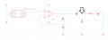
Polarised cap is fine. Value is from a rule of thumb that says that the impedance of the coupling capacitor should be less than a tenth of the impedance of the load. It’s value isn’t critical. But avoid the resonant frequency!
Rules of thumb are much quicker than simulation software. Sometimes you come unstuck, but not very often. That’s why they are rules-of-thumb!

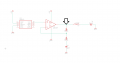
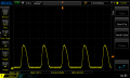
By the way, 74AC125 would be a nice device to drive the coil with a square wave. When switched off, it lets the output float, instead of forcing it to 0V.
 

Thread Starter

8dm7bz

Joined Jul 21, 2020
199
Ok great, thanks for explaining that. I always had trouble before that the wave generated by the generator would collapse under the coil load. Even after I put it through a buffer amplifier. But I guess I never used the right capacitor.

Would the 74AC125 be a substitution for the MCP1401 mosfet drivers ?
 

Ian0

Joined Aug 7, 2020
9,680
True, but the load current is only 9.3mA.
1.46mH inductance @ 20kHz = 183Ω
2.5V rms into 180Ω = 13mA.
plenty of drive from the 74AC125
The reason that your generator output collapses is that there was net DC across the inductance. In that case the current is determined by the Voltage divided by the DC resistance of the coil. 5V divided by 3.2Ω = 1.5Amps.
 

Thread Starter

8dm7bz

Joined Jul 21, 2020
199
Ok, so I tried building one of the circuits you suggested @Ian0 with stuff I already have on hand. I tried the one where I used an op amp and attached the measurments. I read your latest response, and the way I understand it, I just need to remove the dc part. So I thought why not a high pass filter ? The op amp in use is the LM358P, it might not be the best for the job, but that's the one I had on hand. If the op amp is the problem please let me know. I marked the oscilloscope test points with the arrow, always with reference to ground.

File1 is the output of the AD9833 through the non inverting op amp.
File2 is the output of the AD9833 through the non inverting op amp and then through the high pass filter.
File3 is the same as File2 but under a load, specifically one of those coils.
File4 is the same as File 1 but under a load, with the same coil as in File3.

Then I tried to pick up the signal with one of those coils. And I found that I get the strongest signal using the setup of File4.

I would like to know what I'm doing wrong ?

thanks,
8
 

Attachments

Ian0

Joined Aug 7, 2020
9,680
Erm . . the 2.2uF capacitor IS your high pass filter. (When its main purpose is to remove the DC offset, then it's generally just called a "coupling capacitor").
You introduced a 47nF capacitor in series with the 2.2uF capacitor. Formula for 2 capacitors in series gives 46nF for the combination. Impedance of 46nF @ 20kHz is 173 ohms. (Forget the 1M resistor - it's not doing anything)
You are using the lower inductance of the two coils: 370uH has an impedance of 46 ohms at 20kHz. That needs 38mA rms or 54mA peak to drive it from 5V, and that's rather more than the LM358 can manage. At 20kHz you really need the higher inductance coil, or an op-amp with rather more output current, such as the AD8616 used in the Whitmier, Patel and Parizi paper. Also a LM358 is a really slow op amp!
Your gain setting in file 2 is also wrong. You have a DC gain of 4.25, and you signal has an average DC level of 2.5V. The OP amp is going to be trying its best to give you an average DC level on the output of 10.63V (and it's not going to succeed!). Your input signal is 2.5V peak/peak. You can only get 5V peak/peak so your AC gain can be no more than 2, and the DC gain must be 1.
 

Thread Starter

8dm7bz

Joined Jul 21, 2020
199
Ok, so I understand why my resistor does nothing, and the second capacitor is not doing the job I intended it to do.
And I guess I understand why I would need a higher inductance. Let's say I take a coil with 1.45mH inductance. That would make 182 ohms at 20kHz which in turn would need roughly 20mA at 5V. I think that's doable for the LM358, right ?

I don't quite understand the problem with the op amp though. When I output a 20kHz sine wave from the AD9833 it gives me 600mV peak to peak. So I thought I can amplify it with a gain of 4.25 ? Could you elaborate on this a little more please

thanks,
8
 

Ian0

Joined Aug 7, 2020
9,680
You're correct - I misread it, and thought it was the output from the AD8933.

Correct about 182 ohms, but now that the signal is AC, it is 5V peak-to-peak, but that's 2.5V peak or 1.76V rms. So the peak current will be 13mA.
The LM358 gives a maximum output current of 20mA source, but only 8mA sink, so it will manage the top half (just) but fail on the bottom half.
Slew rate limits the output to 6V peak-to-peak at 20kHz, and the open-loop gain at 20kHz is only 30dB: enough, but it will be starting to mess up your gain calculations. Calculated gain of 4.25 will have a real gain of only 3.7.
Higher inductance coil will have another advantage - it will have more turns, which will make more magnetic field.
 

Thread Starter

8dm7bz

Joined Jul 21, 2020
199
Ok, I think I understand. But could you sketch a circuit with AD8616 and the right resistor values for the gain please. So I can reinforce my understanding. Because I feel like I'm walking a very slippery slope ^^"

thanks,
8
 

Ian0

Joined Aug 7, 2020
9,680
You're values are correct except that you need a capacitor in series with R2 to reduce the DC gain to unity.

I would suggest that you use 10k and 32.5k instead of 100 ohms and 325 ohms otherwise it takes a lot of the amplifier's output current just to drive the resistors (us mere mortals would use 33k and have nothing to do with the pretentious E96 series!)

To reduce the gain to unity at DC, the capacitor impedance needs to have no effect on the gain at 20kHz, so choose it to have an impedance at 20kHz of 10% of the resistor value . i.e. 1k ohm (that's using my 33k/10k resistor combination) so any capacitor bigger than 8nF will do the job.

(Using 325/100 ohms your capacitor would need to have an impedance of <10 ohms at 20kHz, so a value of >800nF, but it can be polarised)
 

Ian0

Joined Aug 7, 2020
9,680
I made the assumption that the output would be centred on mid-supply like it is for all audio DACs, but it isn't (should've read the datasheet!). It's centred on 0.3V, so you need to shift the DC level to half supply.
So, from the non-inverting input of your op-amp take a resistor to ground, and another resistor of the same value to the positive supply, which will bias it to 2.5V. Use a large value of resistor.
Then connect the AD9833 output to the same point with a capacitor.
Capacitor impedance should be small compared to the value of the resistors, and bear in mind that from the point of view of an AC signal the resistors look like they are in parallel*. (When you draw the diagram they may look like they are in series)
So for 100k resistors, parallel combination = 50k. choose capacitor impedance <5k. >1.5nF at 20kHz.

*Do you understand why they appear to be in parallel?
 

Thread Starter

8dm7bz

Joined Jul 21, 2020
199
Ok I made the changes and got some clipping at the top, so I now have 110k ohms from 5V to the non inverting input and 100k to ground (now I get a clean signal). And then I used a 10nF cap in series with the input. That works really good.
Yes, when I draw the diagram I can see why they seem to be in parallel for the input signal.

But when I connnect the load and measure between op amp output and ground the signal still collapses :/
 

Attachments

Ian0

Joined Aug 7, 2020
9,680
One thing about the LM358. It's not rail-to-rail. It can get to the bottom rail, but not the top. It can't get closer than 1.5V to the top supply. That's 3.5V, on a 5V supply, so you can only hope for 1V output.
If you don't have a rail-to-rail op-amp (there are plenty to choose from, you don't necessarily need the fancy Analog Devices part, but you need a quick one!) connect the LM358 V+ to a few more volts (anything from 7V to 32V).
If you've only got 5V, and can't lay your hands on a better op-amp at the weekend, bias the input a little lower (1.7V instead of 2.5V) ; and reduce the gain so that the output current doesn't exceed the LM358's 8mA maximum
This
http://sim.okawa-denshi.jp/en/teikokeisan.htm
saves a lot of time working out resistor values!
 

Thread Starter

8dm7bz

Joined Jul 21, 2020
199
ok, I tried powering the op amp with a 9V battery without any real improvement. Then I tried lowering the bias and even using the op amp as a buffer amplifier configuration, the voltage still collapses across the coil. And when I used it as a buffer amplifier it should only need to sink and source around 1.5mA with a 600mV peak to peak, right ?

But then I thought back when you said that the impedance of the 2.2uF cap at the end should be around 10 times smaller than that of the inductor. And since I changed the coil to the higher inductance one, I think I need to change the capacitor aswell ? Anyways the impedance of the coil is around 190 ohms, so I tried a 0.47 uF capacitor which would give me 17 ohms. I think it helped a little.
Next I tried a 220pF cap. Just to see what would happen. It didn't collapse, but it would give me a 360k ohms impedance at 20kHz, so that doesn't sound right.

I feel though it has something to do with the cap at the end maybe ?
 

Ian0

Joined Aug 7, 2020
9,680
Try a better op-amp before you give up.
Maybe the slow old LM358 doesn't like the phase response of the inductive load at that frequency - try some series resistance, probably about the same as the coil impedance - 180 ohms.
By the way - the cap requirement was LESS than a tenth of the impedance, so 2.2uF would be marginally better than 470nF.
 

Thread Starter

8dm7bz

Joined Jul 21, 2020
199
Yes, I will get some better op amps. Another cap I tried is 47nF, that is near resonant frequency. But that would give me the best response on a receiver coil. Why isn't that good ?
 

BobTPH

Joined Jun 5, 2013
8,816
But that would give me the best response on a receiver coil. Why isn't that good ?
It depends on what you are trying to do. As already pointed out, driving the inductance at 20KHz and 5V will give you only a few mA.

I might have missed it, but I have not seen anything to indicate how much current you want.

If you want more currrent, you use a series capacitor to cancel some or all of the inductance. At resonance, the impedance is 0 (actually just the series resistance.)

And why do you insist on driving it with an opamp, a low current device? Using a pair of MOSFETs could get you Amps. You don’t need a linear amp for a square wave!

Circuits for wireless power drive a series resonant circuit and control the frequency to control the power delivered.

Bob
 

Ian0

Joined Aug 7, 2020
9,680
It depends on what you are trying to do. As already pointed out, driving the inductance at 20KHz and 5V will give you only a few mA.

I might have missed it, but I have not seen anything to indicate how much current you want.

If you want more currrent, you use a series capacitor to cancel some or all of the inductance. At resonance, the impedance is 0 (actually just the series resistance.)

And why do you insist on driving it with an opamp, a low current device? Using a pair of MOSFETs could get you Amps. You don’t need a linear amp for a square wave!

Circuits for wireless power drive a series resonant circuit and control the frequency to control the power delivered.

Bob
Bob, 8dm is building the circuit from this paper
https://ubicomplab.cs.washington.edu/pdfs/aura.pdf
You can call me an old cynic but this paper gives me a don't-know-anything-about-circuit-design-but-I-know-how-to-code vibe.
For instance why are the coils time division multiplexed when they could be driven at different frequencies and tuned out in the receiver?
I think the transmitting amplitude needs to be known so that the range can be estimated, and something has to limit the coil current other than the power supply, hence avoiding resonance; but I suggested square wave drive a few pages back.
Square wave voltage waveform = triangle wave current = near enough a sinewave for me.
 

Thread Starter

8dm7bz

Joined Jul 21, 2020
199
Yes I want to try the MOSFET variant too. That is just not what I had on my hands at the time. So I wanted to know how far I could get with the op amps, since I had a few laying around. I will go and design a circuit around the MOSFET variant to see what parts I need and then go and buy them from somewhere. I just didn't want to buy half now and half later because shipping is quite expensive.

And current wise, yes you are right I haven't really mentioned it. I thought that the guys from this paper knew what the best method is, so I figured I would just kind of go with their approach. But the point of the paper is to use 3 coils as a receiver and 3 coils as a transmitter, to estimate the distance between those 2. And I guess I need as much current as possible for it to work best ? (please correct me if I'm wrong)

I will design the circuits and post them here, to see if I forgot some parts.

thanks,
8
 
Top