Facebook
 Google
 GitHub
 Linkedin
Hello,
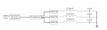
so what I've got is an AD9833 (https://www.analog.com/media/en/technical-documentation/data-sheets/AD9833.pdf) waveform generator. I use it to generate a 20KHz square wave, 5Vpp. Now I want to drive a so called 3D coil cube (https://www.grupopremo.com/3dcc28-3...tions-395x395x386mm-/1982-3dcc28-a-0150j.html).
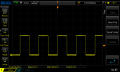
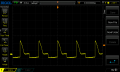
My problem is that whenever I start the AD9833 everything works fine and I get a nice and clean looking square wave at 20KHz. But when I now connect one of the coils to lets say pin 1 and pin 2, the square wave kind of collapses. My guess would be to match the impedances, but since I never did this I don't know how to do that.
Any suggestion to whats going on is appreciated.
P.S. I use an AD9833 module from amazon: https://www.amazon.de/TECNOIOT-AD98...child=1&keywords=Ad9833&qid=1597668925&sr=8-1
thanks,
8dm7bz
so what I've got is an AD9833 (https://www.analog.com/media/en/technical-documentation/data-sheets/AD9833.pdf) waveform generator. I use it to generate a 20KHz square wave, 5Vpp. Now I want to drive a so called 3D coil cube (https://www.grupopremo.com/3dcc28-3...tions-395x395x386mm-/1982-3dcc28-a-0150j.html).
My problem is that whenever I start the AD9833 everything works fine and I get a nice and clean looking square wave at 20KHz. But when I now connect one of the coils to lets say pin 1 and pin 2, the square wave kind of collapses. My guess would be to match the impedances, but since I never did this I don't know how to do that.
Any suggestion to whats going on is appreciated.
P.S. I use an AD9833 module from amazon: https://www.amazon.de/TECNOIOT-AD98...child=1&keywords=Ad9833&qid=1597668925&sr=8-1
thanks,
8dm7bz