Facebook
 Google
 GitHub
 Linkedin

Hello there
Thanks in advance for your time. I would like to have the opinion of the experts here.
A few months ago I bought a 12V Strobe Module with a xenon flash tube from a company called XenonFlashTubes. By the way it stopped their business without any previous notice some months ago and their web page went down.
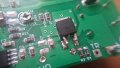
(Pictures of the original Board)


Well back to the topic.......The brightness emitted by this card was not as strong as expected then I wrote to the manufacturers and they responded this at the time:
The setup of two additional capacitors as I suggested will give 32J which is almost like a camera flashgun.
after the modification I suggested, you will get a 32J flash every 4 seconds or so. (not exact number)
The stock factory capacitor for this board gives about 0.35J per flash.
You can connect two capacitor in series, each 330v 560uF, it will make a 660v 280uF capacitor.
charged to the module's output of 480v+, it will give you 32 Joules.
It is comparable to almost full power professional camera flashgun.
it will take about 3-4 seconds to charge, so it will flash every 3 seconds or so
Finally I changed the polyester capacitor included for a electrolytic one. I think is a 100uf 440V.

Things were good for some days using it from 2 to 10 minutes laps per day but something went wrong after and the flash didn't work again. I would like to know where the error was and if it is feasible to fix the module and what tests I could do. The capacitor appears to charge perfectly but there is no flash. The stock mosfet was changed for a more robust one (replacement) but it didn't work either. The reference for the new one was IPP110N20NA


I dont know what else to do
They promoted this board as a "customizable" module in terms of the capacitors used in order to perform brightness and flash rate changes.
By the way At the time of the failure in the enclosure where the board was installed, a very small residue was observed, apparently coming from the small triggercoil flyback.
Maybe I forgot to take into account the heating that occurs in the card after the change. I dont know :-( :-(
Also I do not know if it was necessary to place a "protection" diode that a friend recommended me and that I forgot to weld

This is my first message in this valuable forum. Sorry for the mistakes
Thank you!!
Thanks in advance for your time. I would like to have the opinion of the experts here.
A few months ago I bought a 12V Strobe Module with a xenon flash tube from a company called XenonFlashTubes. By the way it stopped their business without any previous notice some months ago and their web page went down.
(Pictures of the original Board)
Well back to the topic.......The brightness emitted by this card was not as strong as expected then I wrote to the manufacturers and they responded this at the time:
The setup of two additional capacitors as I suggested will give 32J which is almost like a camera flashgun.
after the modification I suggested, you will get a 32J flash every 4 seconds or so. (not exact number)
The stock factory capacitor for this board gives about 0.35J per flash.
You can connect two capacitor in series, each 330v 560uF, it will make a 660v 280uF capacitor.
charged to the module's output of 480v+, it will give you 32 Joules.
It is comparable to almost full power professional camera flashgun.
it will take about 3-4 seconds to charge, so it will flash every 3 seconds or so
Finally I changed the polyester capacitor included for a electrolytic one. I think is a 100uf 440V.
Things were good for some days using it from 2 to 10 minutes laps per day but something went wrong after and the flash didn't work again. I would like to know where the error was and if it is feasible to fix the module and what tests I could do. The capacitor appears to charge perfectly but there is no flash. The stock mosfet was changed for a more robust one (replacement) but it didn't work either. The reference for the new one was IPP110N20NA
I dont know what else to do
They promoted this board as a "customizable" module in terms of the capacitors used in order to perform brightness and flash rate changes.
By the way At the time of the failure in the enclosure where the board was installed, a very small residue was observed, apparently coming from the small triggercoil flyback.
Maybe I forgot to take into account the heating that occurs in the card after the change. I dont know :-( :-(
Also I do not know if it was necessary to place a "protection" diode that a friend recommended me and that I forgot to weld
This is my first message in this valuable forum. Sorry for the mistakes
Thank you!!
Attachments
-
 82.6 KB Views: 5