double parallel limiter with zeners ad calculate the R

ericgibbs

Joined Jan 29, 2010
21,569
I would say that Vin max is the positive half cycle and Vin min is the negative half cycle, allowing as Jony and I have said about subtracting the zener voltage around each current path.
 

Thread Starter

PsySc0rpi0n

Joined Mar 4, 2014
1,786
The question is that i used the Iz max from zeners potency to calculate that Rs, remember? It was 132.27 ohms? But i would like to do a more real simulation. And I would like to use our teacher's formulas... If i can't get good values, I'll use the values i have!


PS:

I've calculated the Iz min and Iz max for both zeners. Is it a good pratice if I choose a middle value between the 10% and 90% of Iz MAX (calculated from potency)?

I mean, for the 5.6V zener with a 0.5W potency i got an Iz MAX of 79mA. So, Iz max will be 71.1mA and Iz min 7.9mA.
The other zener of 3.9V with a potency of 0.25W i got an Iz MAX of 54mA. So, Iz max is 48.6mA and Iz min is 5.4mA

For the 5.6V, is it a good practice choose the value that is the middle point between Iz min and Izmax??? It would be 31.6mA for the 5.6V zener and 21.6mA for the 3.9V zener...

Do you think I can calculate Rs min and Rs max with these Iz values?
 
Last edited:

Thread Starter

PsySc0rpi0n

Joined Mar 4, 2014
1,786
Well, I have tried with my assumptions, and i got I_rs min of 6.62mA and I_rs max of -11.76mA (considering absolute values).

Though in LTSpice, values differ a little. -12.54mA of I_rs max and 6.64mA of I_rs min...

Is this ok?
 

ericgibbs

Joined Jan 29, 2010
21,569
I've calculated the Iz min and Iz max for both zeners. Is it a good pratice if I choose a middle value between the 10% and 90% of Iz MAX (calculated from potency)?
The mid value between the limits of 10% and 90% is 50% of the zeners rated current!.

So if you did it that way,
0.5/5.6 = ~90mA so 50% = 45mA
0.25/3.9= ~ 64mA, so 50% = 32mA

Personally I would not use these high current values for a limiter.

You say the tutors formula's are
Rs, max= [Vin, min -Vz]/[Iload, max + 0.1*Iz,max]

This would mean the tutor expects you to use 10% of Iz max of the zener. Which I would personally choose.

Which is 9mA and 6.4mA, do you agree.??

Iload is the current thru Rload.

The only Vin, max and Vin, min for that 50Hz sine wave I can see are the +/-Vpeak ie: +/- 8.49V

Calc what you think it is and post your values and the simulation asc file..
 
Last edited:

Thread Starter

PsySc0rpi0n

Joined Mar 4, 2014
1,786
I have done Iz maz = 0.5/(5.6+0.7) = 79mA.
Then 10% = 7.9mA and 90% is 71.1mA.
Then the mid point would be (71.1-7.9)/2 = 31.6mA.

Doing the same for 3.9V zener:

Iz max = 0.25/(3.9+0.7) = 54mA.
Then 10% = 5.4mA and 90% is 48.6mA.
Then the mid point would be (48.6-5.4)/2 = 21.6mA.

Then Rs min = 8.49/31.6 = 268.54Ω
Then Rs max = 8.49/21.6 = 392.84Ω

Rs med = (392.84+268.54)/2 = 330.69Ω

The I_rs for each semi-cycle would be:
I_rs min = (-8.49+4.6)/330.69 = -11.76mA
I_rs max = (8.49-6.3)/330.69 = 6.62mA
 

Attachments

ericgibbs

Joined Jan 29, 2010
21,569
I have done Iz maz = 0.5/(5.6+0.7) = 79mA.
Then 10% = 7.9mA and 90% is 71.1mA.
Then the mid point would be (71.1-7.9)/2 = 31.6mA.

Doing the same for 3.9V zener:

Iz max = 0.25/(3.9+0.7) = 54mA.

0.5/5.6 = ~90mA so 50% = 45mA
0.25/3.9= ~ 64mA, so 50% = 32mA


But you do not want this value...

But as the tutors formula states you want 10% of Iz max


Which is 9mA and 6.4mA, do you agree.??

Then 10% = 5.4mA and 90% is 48.6mA.
Then the mid point would be (48.6-5.4)/2 = 21.6mA.

Then Rs min = 8.49/31.6 = 268.54Ω
Then Rs max = 8.49/21.6 = 392.84Ω

Rs med = (392.84+268.54)/2 = 330.69Ω

The I_rs for each semi-cycle would be:
I_rs min = (-8.49+4.6)/330.69 = -11.76mA
I_rs max = (8.49-6.3)/330.69 = 6.62mA
You do not add the 0.7V diode drop when calculating the Iz max for the zener wattage rating, only add it when you calculate the voltage, in order to calc Rs values.
 

Thread Starter

PsySc0rpi0n

Joined Mar 4, 2014
1,786
How do i calculate R knowing that:

since the output voltage is made from the contribution of the input signal plus the contribution of the capacitor's charge and that the voltage of this capacitor discharges through R with a time constant of tau = R.C, and that it's important ensure that the time constant is 5 times the time the capacitor is discharging, calculate R also knowing that the frequency is 1KHz and the capacitor is 220uF.
 

ericgibbs

Joined Jan 29, 2010
21,569
How do i calculate R knowing that:

since the output voltage is made from the contribution of the input signal plus the contribution of the capacitor's charge and that the voltage of this capacitor discharges through R with a time constant of tau = R.C, and that it's important ensure that the time constant is 5 times the time the capacitor is discharging, calculate R also knowing that the frequency is 1KHz and the capacitor is 220uF.
hi
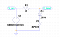
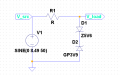
This image is the one you posted for this question, post #41, WHERE is the capacitor on your circuit image.?:confused:

You really must be consistent with your questions and answers, we are still going around in circles, reworking details we have discussed a number of times.

If the question has changed post a new circuit image,
 

Attachments

Thread Starter

PsySc0rpi0n

Joined Mar 4, 2014
1,786
I'm sorry... This is another question...

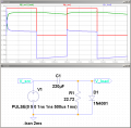
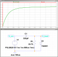
What i know is that tau = R.C, frequency is 1KHz (T=1ms), C = 220uF, and also that tau must be 5 times the time the capacitor is discharging.
 

Attachments

ericgibbs

Joined Jan 29, 2010
21,569
I'm sorry... This is another question...

What i know is that tau = R.C, frequency is 1KHz (T=1ms), C = 220uF, and also that tau must be 5 times the time the capacitor is discharging.
OK, it helps me to understand what you are asking me when you post the question and the circuit/simulation.

What do you calc the answer to be for R1,? show your calculations and we can check them.
 

Thread Starter

PsySc0rpi0n

Joined Mar 4, 2014
1,786
I posted calculations in the previous post.

5 * 1ms = 220μF*R

R = 22.72Ω

But how can I check the 63.2% of the capacitor charge at the 1st tau at the plot???
 

Thread Starter

PsySc0rpi0n

Joined Mar 4, 2014
1,786
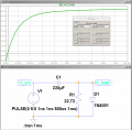
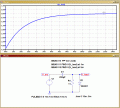
I have done the simulation and changed the X-scale values to try to see where the voltage at the capacitor reaches 63.2 mV... But i get a very small time like 1.6μS
 

Attachments

ericgibbs

Joined Jan 29, 2010
21,569
Try this method, note the .tran settings.

Using Measure, after running the sim pres Cntrl and 'L' keys to see the Error log, read the values at V1m and V5mSec

Note: the time constant effects the Charge time voltage so the Cap will not charge to 5V, so allow for this in your calculations.
 

Attachments

Top