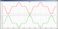
double parallel limiter with zeners ad calculate the R

ericgibbs

Joined Jan 29, 2010
21,569
OK,
I dont think its possible to edit your thread title, a Moderator may do it for you, if you ask.

The way you have the zeners connected is equivalent to a Zener and regular diode in series.
You know the zener voltage and a diodes forward voltage, so calculate the total forward drop of the zener and a diode.
Knowing that total you should be able work out the Rs resistor value, repeat the above for the current flowing thru the zener and diode in the opposite direction..

Obviously the Rs value will be different, so determine a common value of Rs that will be suitable for both zener paths. Ensure the lowest rated Wattage power is not exceeded.

I cannot give you full answers, as this is your Homework.:rolleyes:
Just hints or clues.
 

Thread Starter

PsySc0rpi0n

Joined Mar 4, 2014
1,786
So, i got the follwoing values for both currents:

Iz1 = 54mA

Iz2 = 79mA

Is this correct?

(I'll be doing calculatioon considering only Iz max, said the teacher)
 

ericgibbs

Joined Jan 29, 2010
21,569
Whats the value of Rs.?

Those Iz's seem a little too high, dont forget in a real application its wise to design for low power usage.
 

Thread Starter

PsySc0rpi0n

Joined Mar 4, 2014
1,786
Well, 0.25/(3.9+0.7) = ~0.054 and 0.5/(5.6+0.7) = ~0.079.

The R for one of the semi-cycle is 8.49/0.079 = ~157.13 ohms and for the other semi-cycle is 8.49/0.054 = ~ 107.41 ohms.

The average R will be the sum of those 2 values divided by 2 which is 132.27...

Is this ok?
 

ericgibbs

Joined Jan 29, 2010
21,569
Hi,
Your calc's are wrong somewhere...:)

You dont use the maximum possible current based on the zeners wattage rating to calc Rs..

EDIT:
Try 10% of the 3.9V zeners maximum current rating.
 
Last edited:

Thread Starter

PsySc0rpi0n

Joined Mar 4, 2014
1,786
Well, my teacher told us we could use the max Iz to calculate Rs...

Are you telling me to consider like Iz1 = ~35mA and Iz2 = 60mA??? And calculate R with this I's?
 

ericgibbs

Joined Jan 29, 2010
21,569
If he told you to use Iz max, then you must do it that way if you are to get his approval.

Its not the correct way to calculate Rs..

Your answer is still wrong, why dont you run a LTS simulation using a 132R and check the current..

EDIT:


You said: Iz1 = 54mA Iz2 = 79mA
I make it ~15mA and ~26mA using a 132R
 
Last edited:

Thread Starter

PsySc0rpi0n

Joined Mar 4, 2014
1,786
If he told you to use Iz max, then you must do it that way if you are to get his approval.

Its not the correct way to calculate Rs..

Your answer is still wrong, why dont you run a LTS simulation using a 132R and check the current..

EDIT:


I make it ~15mA and ~26mA using a 132R
How did you got those values??? They match the simulation! :(
 

Thread Starter

PsySc0rpi0n

Joined Mar 4, 2014
1,786
Morning...

Yes, K laws...

But I didn't associated them to this problem. Or better, didn't associated that I needed to subtract the diode+zener voltage to the source voltage!
 

ericgibbs

Joined Jan 29, 2010
21,569
Morning...

Yes, K laws...

But I didn't associated them to this problem. Or better, didn't associated that I needed to subtract the diode+zener voltage to the source voltage!
Morning Psy,

Have you now got the method for solving these zener problems.?:)

Remember as Jony explains, the zener can be replaced with a Vdc source equal to the value of the zener conduction voltage.

I was querying how you calculated 54mA and the 70mA currents. I see now you had not considered the zener voltages.

On the positive half cycle of the sine wave you have [3.9v +0.7v] = 4.6v of 'regulated' voltage. so if the Vsource = 8.49v, thats 8.49v-4.6v = 3.89v across Rs.

You calculated Rs as ~ 132.27R.. +Irs = 3.89/132.27 = ~29mA

For the negative half cycle of Vsrc 5.6 +0.7 = 6.3v

So 8.49v - 6.3v = 2.19v , so -Irs = 2.19v/132.27 = ~16mA

Whenever you calculate a value you should insert that value into you original equation and recalculate in order to check the result.

Whats the next step.?

E
 

Thread Starter

PsySc0rpi0n

Joined Mar 4, 2014
1,786
Morning ericgibbs...

After jony130 tip I was able to do the rest of calculations and confirm them on LTSpice.
Yes, I haven't realised that to calculate the circuit current thru R, I must consider negative/positive voltages from zeners/diodes!


I already have done the rest of the steps of this report which included Voltage multipliers, dividers and a logic port (AND) simulation with diodes!

Now, I need to build my report, add some text explaining the simulations.
This will be done at home with time and relaxation. Though I might need some help.
 
Last edited:

Thread Starter

PsySc0rpi0n

Joined Mar 4, 2014
1,786
I need some help...

I'm considering to recalculate Rs using the Rs max and Rs min formulas, but I don't know what Vin min and Vin max to use...

The formulas I want to use for Rs are the ones from the attachment

Can you help?
 

Attachments

ericgibbs

Joined Jan 29, 2010
21,569
I need some help...

I'm considering to recalculate Rs using the Rs max and Rs min formulas, but I don't know what Vin min and Vin max to use...

The formulas I want to use for Rs are the ones from the attachment

Can you help?
If your zeners and Rs are powered from the earlier full wave bridge, with a Vrms of 6V, then knowing the value of the Cap C1 , you should be able calculate Vmax, Vmin.
 
Top