Facebook
 Google
 GitHub
 Linkedin
Ok so I had a thread here awhile back on a psu I was building. I got busy with other projects and life and it got put on a shelf. It seems that I lost all of my data I had saved for it. So here is what I want to do and what ive got for it.
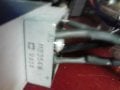
1.) my transformer has the primary and 3 secondaries. The sec. HV coil is center tapped. it is the main one I want to use for my psu. it measures 22.6vac per leg so it should be around 32vdc each leg. im using an mb354-w rectifier bridge so im expecting some voltage drop from it. My intentions are to have a +/- 0-20vdc 4a adjustable supply.
2.) Ill be using (3) LM317's and an nte996(the schematic shows an lm308 but mines the same ic) heres the schematic for that one. page 25 fig 55.
http://www.ti.com/lit/ds/symlink/lm117.pdf
and the schematic for the LM317 with a pass transistor is here. page 2
http://www.ee.teihal.gr/labs/electronics/web/downloads/LM317T_Variable_Voltage_Regulator.pdf
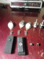
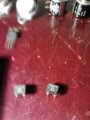
I need to combine these 2 schematics to achieve what I want. which is 3 LM317's using 2n3055's as pass transistors on each LM317.
the nte 996 datasheet is here..
http://pdf1.alldatasheet.com/datasheet-pdf/view/10931/NTE/NTE996.html.
3.) Im using 3 nte2050's with 7seg displays for voltage and amp displays.the datasheet for the nte2050 is here..
http://pdf1.alldatasheet.com/datasheet-pdf/view/9882/NTE/NTE2050.html..
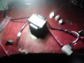
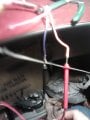
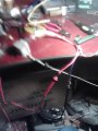
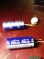
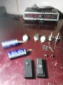
so this is what ive got so far.. I need opinions and help building my schematic so I can start to build.. as always,, thanks
1.) my transformer has the primary and 3 secondaries. The sec. HV coil is center tapped. it is the main one I want to use for my psu. it measures 22.6vac per leg so it should be around 32vdc each leg. im using an mb354-w rectifier bridge so im expecting some voltage drop from it. My intentions are to have a +/- 0-20vdc 4a adjustable supply.
2.) Ill be using (3) LM317's and an nte996(the schematic shows an lm308 but mines the same ic) heres the schematic for that one. page 25 fig 55.
http://www.ti.com/lit/ds/symlink/lm117.pdf
and the schematic for the LM317 with a pass transistor is here. page 2
http://www.ee.teihal.gr/labs/electronics/web/downloads/LM317T_Variable_Voltage_Regulator.pdf
I need to combine these 2 schematics to achieve what I want. which is 3 LM317's using 2n3055's as pass transistors on each LM317.
the nte 996 datasheet is here..
http://pdf1.alldatasheet.com/datasheet-pdf/view/10931/NTE/NTE996.html.
3.) Im using 3 nte2050's with 7seg displays for voltage and amp displays.the datasheet for the nte2050 is here..
http://pdf1.alldatasheet.com/datasheet-pdf/view/9882/NTE/NTE2050.html..
so this is what ive got so far.. I need opinions and help building my schematic so I can start to build.. as always,, thanks