 Facebook
 Google
 GitHub
 Linkedin
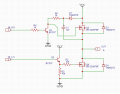
Hello! I want to make an electronic circuit to control a 36V BLDC motor (three phases, hall sensored). I made three half-bridges (like the ones in the picture) for the three connection wires from the motor. I control the bridge with the help of an arduino through the IN_LO and IN_HO pins. At the beginning I fed the circuit with VCC=22V. The motor turned very well, the switching sequence was good. Everything was fine, until I got up the courage and powered the circuit with a VCC=36V battery. The circuit did not like the 36V. Q1 and Q3 from each half-bridge are gone.
How can I improve these half bridges? I would like to try this without IC drivers for each transistor.
How can I improve these half bridges? I would like to try this without IC drivers for each transistor.
Attachments
-
 59.8 KB Views: 63


