Distortion in Active Low Pass Filter

Thread Starter

Green Bean

Joined Mar 31, 2017
126
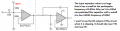
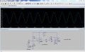
I have breadboarded this simple circuit:

R1, R2 and R4 are 10k digipots being controlled by an Arduino. R3 is a fixed 10k resistor. C1 and C2 are both 100 nF. R1 and R2 always have the same value, so think of them like a dual-gang pot. The op amp is a MCP6023, which is running at +5V (single supply), the digipots are MCP42010s, also running at +5V (and yes all the ICs have decoupling caps). The Arduino produces three square waves which are mixed with three 10k resistors and pass through a 10 uF electrolytic cap before entering the filter. The output of the filter passes through an attenuator (a 1M resistor and a 10k to ground) and a 100 uF electrolytic before going to an amp.

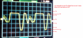
My problem is that I'm getting a lot of unwanted distortion from the filter. The signals are getting clipped a lot when resonance is high (R4 controls the resonance). I really don't like this and I'm not sure what to do. Maybe attenuate the signal before it goes into the filter? I've tried a couple random resistor values and nothing seems to be working. Thoughts?
 

crutschow

Joined Mar 14, 2008
34,408
What are the op amp supply voltages and at what voltage does the op amp clip?

Post a picture of the input and output waveform.
 
Last edited:

Thread Starter

Green Bean

Joined Mar 31, 2017
126
Are those digitpots rated to operate floating without being connected to ground?

What are the op amp supply voltages and at what voltage does the op amp clip?

Post a picture of the input and output waveform.
1. Probably not, but the only pin floating on the chips is the serial out pin, which I think should be ok.
2. The op amp operates between 2.5 and 5.5 V (single supply). I am running it a 5V. As for what voltages it clips, I don't know for sure because I have a really cheap oscilloscope.

3. Well, the resonance and cutoff are variable, so it isn't the same all the time, and even if it was the three signals are constantly "beating" (I think that's the right word) against each other, so the waveform is always changing. AND, like I said, my oscilloscope was $20 (a DIY kit) LOL. But if you insist, here is one example:

Before the filter:
IMG_20180418_2217045_rewind.jpg
After the filter:
IMG_20180418_2216396_rewind.jpg
 

crutschow

Joined Mar 14, 2008
34,408
For the filter output picture, set the input to DC instead of AC and center the trace on the screen with the input grounded.

Edit: Do the same for the input waveform picture.
 
Last edited:

Thread Starter

Green Bean

Joined Mar 31, 2017
126
For the filter output picture, set the input to DC instead of AC and center the trace on the screen with the input grounded.

Edit: Do the same for the input waveform picture.
I'm away from my stuff now, but what do you suspect is causing the distortion? Am I just overdriving the filter?
 

Thread Starter

Green Bean

Joined Mar 31, 2017
126
Ok I added a divider and buffer before the signal enters the filter, so the signal is DC biased. The circuit now looks like this:

Cc is10 uF, RA and RB are both 100k. The opamp is yet another MCP6023 running off the same power supply as everything else. Ok this is all great and seems to be necessary, but I'm still getting the distortion. What do I need to do next?
 

Thread Starter

Green Bean

Joined Mar 31, 2017
126
I get 160 Hz cutoff on this LPF ? Correct ? Using 10Ks in the filter, and
100 nF both caps.

http://sim.okawa-denshi.jp/en/OPstool.php

Are you getting same screen shots on scope ?

Do the screen shots DC coupled on scope.

Regards, Dana.
Yes your calculations are probably correct but the problem is that I'm not trying to just eliminate distortion for a certain frequency, the cutoff and resonance are variable. The resistors aren't fixed. I am basically getting the same results on the scope, but if you insist:

Before filter:
IMG_20180419_1804512_rewind.jpg
After the filter (no DC bias):
IMG_20180419_1806433_rewind.jpg
After the filter (with the DC bias):
IMG_20180419_1807365_rewind.jpg
 

danadak

Joined Mar 10, 2018
4,057
The filter is fundamentally going to take out harmonics, as a LPF,
so that alters waveshape. Additionally as you raise Q you will
get ringing affects, which the filter is displaying in the last photo.
Also when you raise the Q you raise the G, and that in turn, if
increased enough, will saturate the output of the filter OpAmp,
clipping the signal. That's if you take G in the filter OpAmp, right
now G = 1.


Regards, Dana.
 
Last edited:

Thread Starter

Green Bean

Joined Mar 31, 2017
126
The filter is fundamentally going to take out harmonics, as a LPF,
so that alters waveshape. Additionally as you raise Q you will
get ringing affects, which the filter is displaying in the last photo.
Also when you raise the Q you raise the G, and that in turn, if
increased enough, will saturate the output of the filter OpAmp,
clipping the signal. That's if you take G in the filter OpAmp, right
now G = 1.


Regards, Dana.
Yes, I understand that the wave shape is altered from the filter. That's the point. My problem is the clipping. I need to eliminate the clipping. I would like to remove harmonics from the original signal and amplify the harmonics near the cutoff frequency, without the filter clipping the output. From your post it sounds like I need to eliminate (or at least minimize) "G" to stop the clipping. What exactly is "G" and how do I stop the filter from clipping the output?

EDIT:
Is G gain? I think that I'm just overdriving the filter. What I think would help is heavily attenuating the signal before it goes to the filter. That way, even with high gain the signal will not be clipped. Does this sound correct? How would I do this?
 
Last edited:

danadak

Joined Mar 10, 2018
4,057
Yes G = Gain, but in this case where you are using the OpAmp in the filter with G = 1.

The last scope captures you showed are AC coupled, set you scope for DC and look
to see if you have a signal at input to filter offset, such that output is offset. I am lost as
to why the clipping. Maybe do a spice sim to see if there is something both of us are
missing.

Attenuating signal would be a start, but still not explain, with G = 1, if input is not
clipping the output should not either.

Whats the load on output of filter ? In impedance ? Scope probe like 1M ohm or 10M ohms ?

Regards, Dana.
 

Thread Starter

Green Bean

Joined Mar 31, 2017
126
Yes G = Gain, but in this case where you are using the OpAmp in the filter with G = 1.

The last scope captures you showed are AC coupled, set you scope for DC and look
to see if you have a signal at input to filter offset, such that output is offset. I am lost as
to why the clipping. Maybe do a spice sim to see if there is something both of us are
missing.

Attenuating signal would be a start, but still not explain, with G = 1, if input is not
clipping the output should not either.

Whats the load on output of filter ? In impedance ? Scope probe like 1M ohm or 10M ohms ?

Regards, Dana.
I don't have spice, but I'll try to get it and run a simulation soon. The load on the output? I don't know about the scope, but the signal normally goes through a divider (1M and a 10K to ground), through a 100 uF cap and then out to a guitar amp. Maybe the amplifier is causing the problem? Should I try a buffer on the output or something?

EDIT: Even when I'm not running the signal into the amp (only into the scope), I still get the clipping.
 

Thread Starter

Green Bean

Joined Mar 31, 2017
126
IMG_20180420_1734368_rewind.jpg
The line is +5V. 0V is the bottom of the screen (to the right of line in the picture). Here is a signal:
IMG_20180420_1737246_rewind.jpg
Notice that the bottom of the signal is slightly offset from the ground. The more that I increase the cutoff frequency determining resistors, the further away from ground the signal gets. Fortunately though, if I attenuate the signal with a voltage divider after it comes out of the buffer, I get less distortion, which tells me that the filter was being overdriven. Ok, but now when I divide the signal by 2 I get more clipping on the negative edge of the signal. How to attenuate and get no clipping? Here is a signal:
Not attenuated:
IMG_20180420_1820132_rewind.jpg
Attenuated (less clipping, but now it's on the bottom):
IMG_20180420_1819510_rewind.jpg
I replaced the big "earthquake" (lol) cap with 100 nF, and yes vcc is 5v.
 

danadak

Joined Mar 10, 2018
4,057
There is something we do not understand here.

If I take a sine and feed it ac coupled into input buffer/bias network, I should see that exact
waveform out, offset Vcc/2 due to bias network. If this is not happening some part
is faulty.

Then if that is passed to a unity G LP filter, in band, that sine signal should also
appear on output of filter, same Vcc/2 offset, same amplitude, no distortion. If those
conditions are not met again some part is faulty.

Try this with sine if you can.

Regards, Dana.
 

danadak

Joined Mar 10, 2018
4,057
Here is a sim that works.

Blue trace output of first buffer, green output of filter. AC analysis
shows filter peaking at ~ 100, G ~ -2 db.

OpAmp is ~ equivalent to your MCP6023.

Regards, Dana.
 

Attachments

Top