 Facebook
 Google
 GitHub
 Linkedin
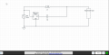
I am building a circuit which would remove any harmonics(despite the fundamental frequency) of a non-linear load driven by a AC voltage source.
The idea is to isolate the harmonics and create a 180 degrees phase shift between the current which contains only the harmonics and the current which contains both the fundamental frequency and the harmonics then sum up those 2 currents.
But the high pass filter will inevitably load C2 so I dont think I can use a 1 stage high pass filter because the overall phase shift wont be 90 degrees between IC2 and V2 but a little less.Which kind of high pass filter would you suggest me use?
Attachments
-
 103.6 KB Views: 5


